Slab cart

a technology for slab carts and slabs, applied in the field of slab carts, can solve the problems of not being suitable for the purpose, affecting the stability of the slab cart, and the ability to shift and lock the slab car

Inactive Publication Date: 2013-01-08
SMITH PHILLIP J
View PDF31 Cites 39 Cited by
  • Summary
  • Abstract
  • Description
  • Claims
  • Application Information

AI Technical Summary

Benefits of technology

[0014]ANOTHER OBJECT of the present invention is to provide a slab cart that is simple and inexpensive to manufacture.
[0015]STILL ANOTHER OBJECT of the present invention is to provide a slab cart that is simple to use.

Problems solved by technology

When a panel is placed in the panel bracing mechanism, the weight of the panel causes braces to shift and lock the panel in place.
Furthermore, even though these innovations may be suitable for the specific individual purposes to which they address, accordingly, they would not be suitable for the purposes of the present invention as heretofore described.

Method used


Image

  • Slab cart
  • Slab cart
  • Slab cart

Examples


Embodiment Construction

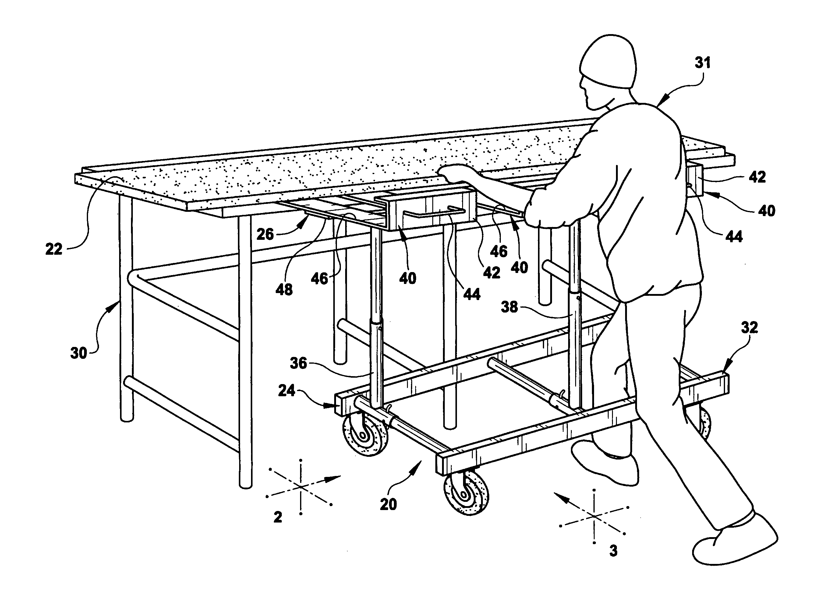
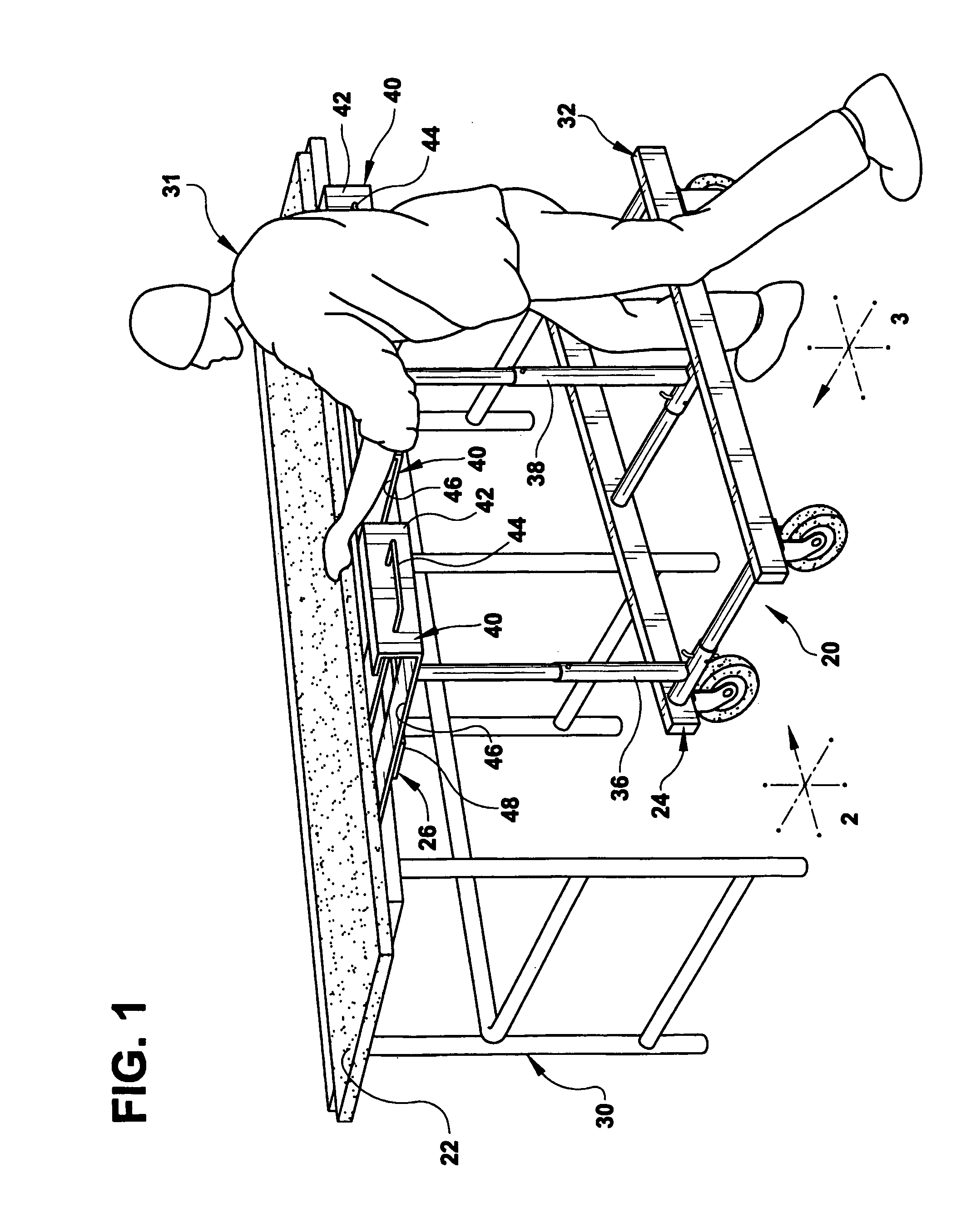
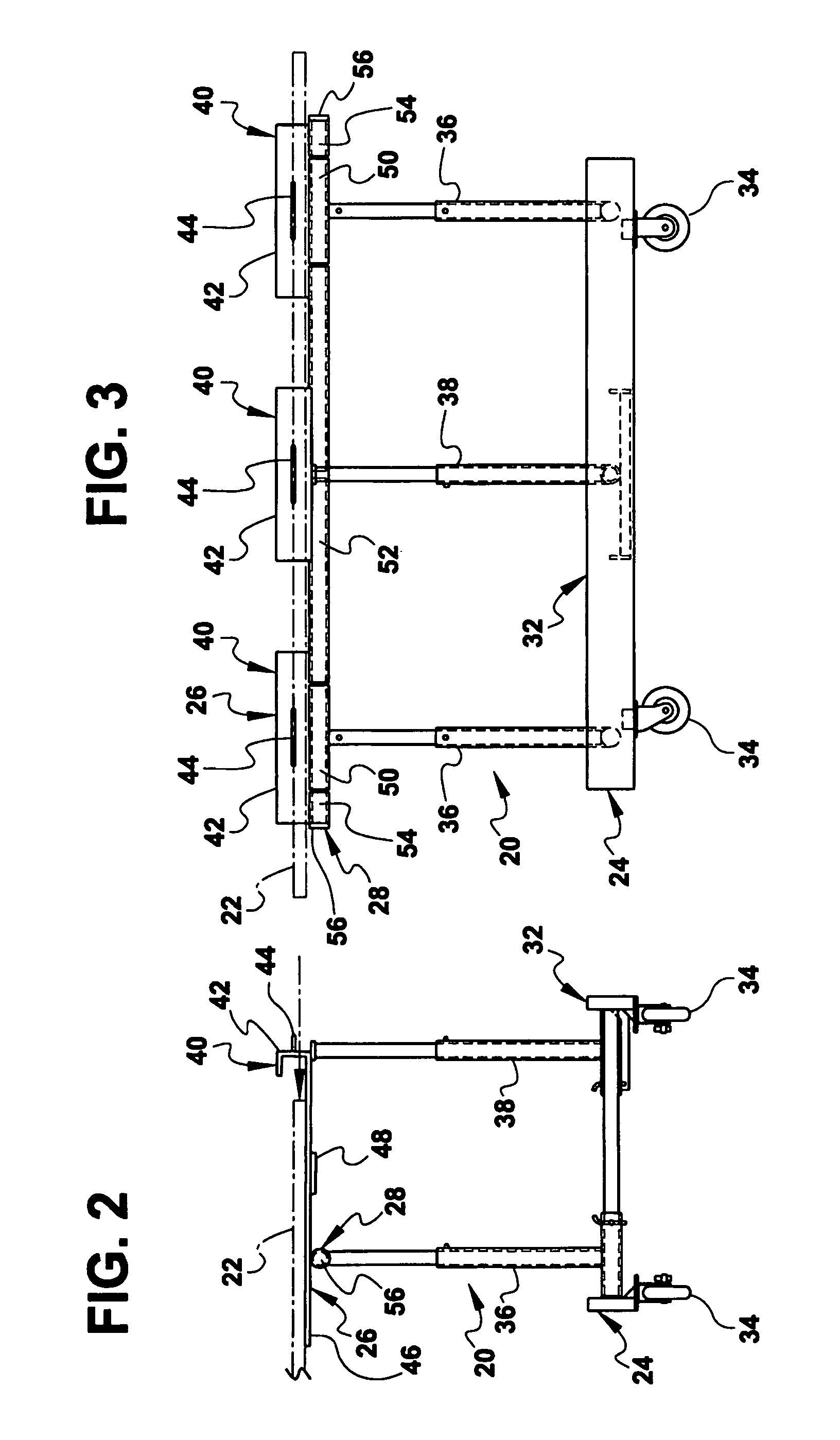
[0049]Referring now to the figures, in which like numerals indicate like parts, and particularly to FIGS. 1 through 10, which are a diagrammatic perspective view of an embodiment of the present invention in use; a diagrammatic end view of the present invention per se, taken in the direction of arrow 2 in FIG. 1; a diagrammatic front view of the present invention per se, taken in the direction of arrow 3 in FIG. 1; a diagrammatic perspective view of the present invention per se, with the shelf component in a vertical position; a diagrammatic end view taken in the direction of arrow 5 in FIG. 4; a diagrammatic front view taken in the direction of arrow 6 in FIG. 4; a diagrammatic perspective view of the present invention separated into separate components as a preliminary step for facilitating transporting the present invention in a pickup truck or similar conveyance; a diagrammatic perspective view of the shelf component of the present invention with the long shaft components stored ...


PUM


Abstract

A slab cart for sheet material which comprises a dolly component. A shelf component receives the sheet material. A mechanism is for coupling the shelf component to the dolly component in a pivotable manner, so that the shelf component will go from a horizontal position to a vertical position. When the shelf component is in the horizontal position the sheet material will be manually slid off of the shelf component onto a support table and be manually slid from the support table onto the shelf component. When the shelf component with the sheet material is in the vertical position, the sheet material will be held on edge to the shelf component and be transported by the dolly component through the confines of narrow places.

Description

BACKGROUND OF THE INVENTION[0001]1. Field of the Invention[0002]The present invention relates to a cart, and more particularly, a slab cart.[0003]2. Description of the Prior Art[0004]Numerous innovations for material handling carts have been provided in the prior art that will be described. Even though these innovations may be suitable for the specific individual purposes to which they address, however, they differ from the present invention.[0005]A FIRST EXAMPLE, U.S. Pat. No. 2,816,771, Issued on Dec. 17, 1957, to Hunt teaches a dolly comprising an elongated substantially U-shaped article receiving frame that includes a pair of spaced side members having one of their respective adjacent ends connected by a bight portion, leg members arranged in depending relation at opposite ends of the bight portion, one of the side members projecting upwardly from the bight portion and outwardly therefrom at an obtuse angle relative thereto and having a projecting portion extending upwardly abov...

Claims


Application Information

Patent Timeline
Patent Type & Authority Patents(United States)
IPC IPC(8): B62B3/04
CPCB62B3/04B62B3/108B62B2203/07B62B2203/70B62B2206/02B62B2206/06
Inventor SMITH, PHILLIP J.
Owner SMITH PHILLIP J
Why Eureka
Try Eureka