Mechanical locking of floor panels with vertical snap folding

a technology of locking system and floor panel, applied in the direction of magnets, magnets, walls, etc., can solve the problems of short edge damage, difficult and unreliable installation, and disadvantage of flexibility

Active Publication Date: 2013-01-15
VÄLINGE INNOVATION AB
View PDF240 Cites 203 Cited by
  • Summary
  • Abstract
  • Description
  • Claims
  • Application Information

AI Technical Summary

Benefits of technology

[0027]Embodiments of the present invention aim at a set of floor panels or a floating flooring with a mechanical locking system, which will improve installation of floor panels installed with vertical snap folding.

Problems solved by technology

The long edge friction makes installation difficult and unreliable and there is a considerable risk that the locking system on the short edge will be damaged.
This flexibility must however be combined with two other features where flexibility is a disadvantage.

Method used


Image

  • Mechanical locking of floor panels with vertical snap folding
  • Mechanical locking of floor panels with vertical snap folding
  • Mechanical locking of floor panels with vertical snap folding

Examples


Embodiment Construction

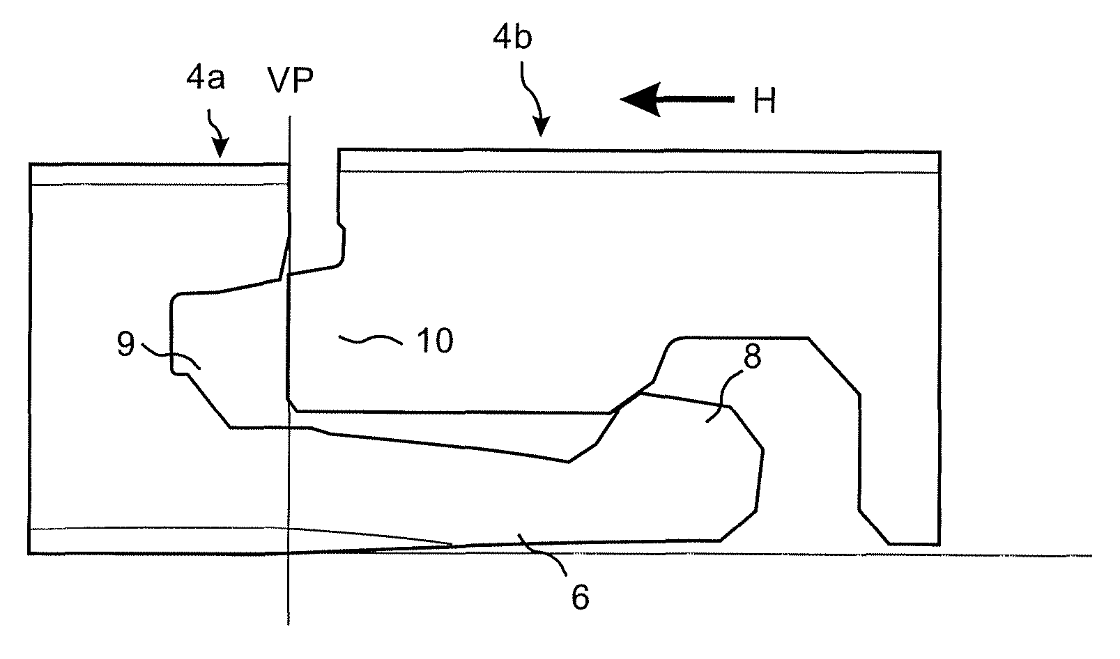
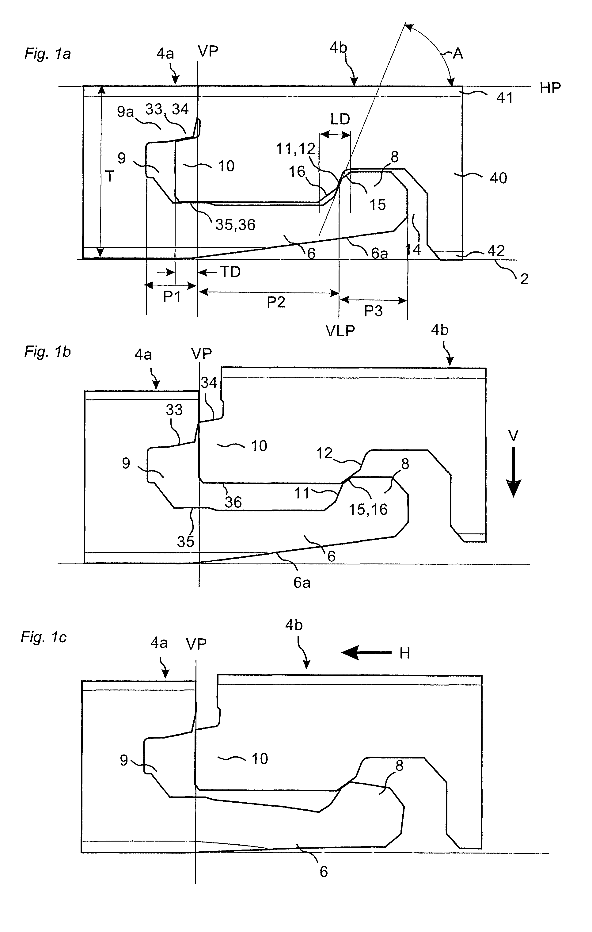
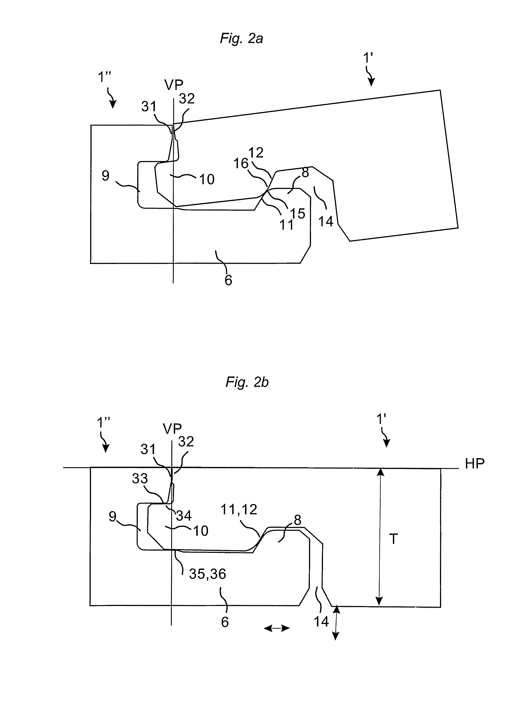
[0063]FIG. 1a shows a locking system that could be used to lock adjacent edges of essentially identical panels, comprising a core 40, a surface layer 41 and a balancing layer 42, vertically and horizontally and that could be used to install panels with a vertical snap folding action. The locking system has a strip 6 extending from a vertical plane VP with an upwardly extending locking element 8 in a first panel edge 4a and a downwardly open locking groove 14 in a second adjacent panel edge 4b. The locking element 8 cooperates with the locking groove 14 and locks the adjacent edges 4a, 4b in a horizontal direction perpendicular to the vertical plane VP and parallel to a horizontal plane HP. The locking system has a tongue 10 in the second panel edge 4b, the folding panel, extending from the vertical plane VP and a tongue groove 9 in the first panel edge, the strip panel, for vertical locking of the adjacent edges. The strip 6, locking element 8, the locking groove 14, the tongue 10 a...


PUM


Abstract

Floor panels are shown, which are provided with a mechanical locking system on long and short edges allowing installation with vertical snap folding that could be accomplished automatically without tools and where the short edge locking system has a tongue made in one piece with the panel.

Description

PRIORITY[0001]The present application claims the benefit under 35 USC § 119(e) of U.S. Application Ser. No. 60 / 986,077, filed on 7 Nov. 2008, which is herein expressly incorporated in its entirety.AREA OF INVENTION[0002]The invention generally relates to the field of floor panels with mechanical locking systems, which could be locked by a vertical snap folding. The invention provides new improved locking systems, floor panels with such locking systems and an installation method to connect such panels.BACKGROUND OF THE INVENTION[0003]In particular, yet not restrictive manner, the invention concerns a mechanical locking system for rectangular floor panels with long and short edges. It should be emphasized that long and short edges are only used to simplify the description. The panels could also be square. However, the invention is as well applicable to building panels in general. More particularly the invention relates to the type of mechanically locking systems, which allow that all ...

Claims


Application Information

Patent Timeline
Patent Type & Authority Patents(United States)
IPC IPC(8): E04B2/00H04M1/7246
CPCE04F15/02E04F15/02038E04F2201/0146E04F2201/0161E04F2201/022E04F2201/026H01F7/0252H04M1/0264H04M1/04H04M1/185H04M1/21H04M1/7246E04F13/0894E04F15/02033E04F15/107E04F2201/0138E04F2201/0153H01F7/122H04M1/0256H04M1/0262H04M1/0279
Inventor PERVAN, DARKOSTAHL, MARCUS NILSSON
Owner VÄLINGE INNOVATION AB
Why Eureka
Try Eureka