
Method for increasing the dynamic measuring range of test elements based on specific binding reactions

a specific binding reaction and dynamic measurement technology, applied in the field of analytical test devices, can solve the problems of inability to quantitatively detect any concentration of analyte in the sample, limited detection optics sensitivity, and measurement rang

Active Publication Date: 2013-01-15
ROCHE DIAGNOSTICS OPERATIONS INC
View PDF28 Cites 6 Cited by
  • Summary
  • Abstract
  • Description
  • Claims
  • Application Information

AI Technical Summary

Benefits of technology

[0021]It is against the above background that the present invention provides certain unobvious advantages and advancements over the prior art. In particular, the inventors have recognized a need to extend the dynamic measuring range of test elements based on specific binding reactions and especially of immunological test elements towards higher analyte concentrations where in particular this should be made possible without impairing the lower detection limit.

Problems solved by technology

With the immunological test devices of the prior art it is not possible to quantitatively detect any concentrations of the analyte in the sample.
Towards the lower end, i.e., with regard to the lower detection limit, the measuring range is for example limited by the affinity and selectivity of the binding partners (usually antibodies) that are used and by the sensitivity of the detection optics which is limited with regard to the labels that are used.
Thus in the case of analytes which can occur in very high concentrations in the sample, it is often not possible to provide an adequate amount of binding partner in the test device.
In particular, in the analyte detection zones and control zones where the binding partners are arranged in a very restricted space on the test device, it is not possible to accommodate as much binding partner as would be desired.
This can be particularly problematic in those cases in which a low detection limit for the analyte is required (and one therefore endeavors to concentrate the binding partners in the detection zone as strongly as possible, i.e., to accommodate them in a restricted space and thus due to the limited availability of binding sites on the test device only a relatively small amount of binding partner can be provided) but the analyte can be present in the sample in very variable amounts, i.e., very low as well as very high analyte concentrations can occur.
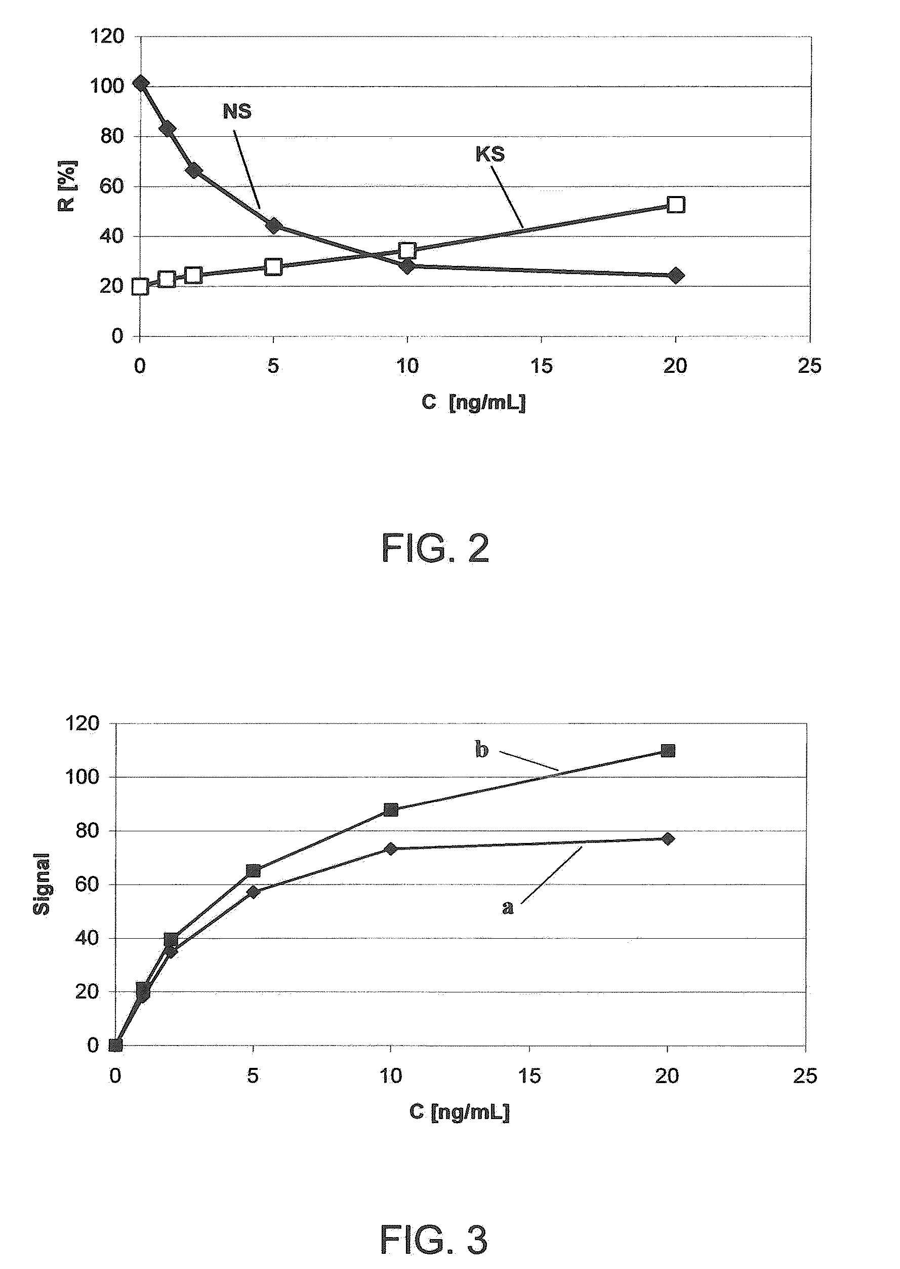
At high analyte concentrations the detection zone is saturated with corresponding detection reagents resulting in a saturation behavior of the analyte concentration-detection signal relationship: The detection signal no longer increases above a certain analyte concentration, the evaluation curve levels off and can no longer be appropriately evaluated.
This is explained by the fact that the amount of antibody offered in the test is no longer sufficient to form a sandwich complex (i.e., a complex comprising two antibodies per antigen) with the analyte molecules (antigens) in every case.
There is an increasing formation of complexes consisting of analyte and in each case one antibody which, however, on their own are no longer detected.
Especially the quantitative immunological test strips in which a signal is determined by reflectance measurements, still have in some cases considerable weaknesses compared to conventional analytical systems that are usually used in large laboratories.
In particular, the precision and the dynamic measuring range is usually worse in the case of test strips.
This limits in particular the field of application of the highly sensitive sandwich assays for example for therapeutic monitoring where the largest possible measuring range is desired.
However, up to now none of the proposals has been convincing in all points.
In particular, the implementation of the concepts in the field of immuno-chromatographic test devices has not satisfactorily succeeded up to now.
A disadvantage of this is that an automatic evaluation of the binding zones requires a relatively complicated optical system which is able under certain circumstances to simultaneously detect and evaluate a large number of zones in order to thus allow a quantitative analyte determination.
Moreover, the test devices have to be relatively long due to the relatively large number of discrete binding zones that are spatially separated from one another.
Thus in order to ensure that the sample reliably migrates through the test device, it is necessary to use relatively large sample volumes which especially if it is intended to use whole blood samples, is also disadvantageous especially for reasons of sample collection.
An extension of the measuring range achieved in this manner is unsatisfactory since it requires additional handling steps that could potentially lead to errors in the analysis.
Furthermore, especially in cases in which an analyte could occur in very high as well as in very low concentrations in similar samples, a controlled sample dilution is only advisable when the analyte is present in the sample at high concentrations but not in the reverse case since otherwise the concentration may fall below the lower detection limit as a result of the dilution and the analyte may be falsely not detected in the sample.
There has been previously a lack of simple and reliable methods for extending the dynamic measuring range of immunochromatographic test devices towards higher analyte concentrations without adversely affecting the lower detection limit for the analyte detection.

Method used


Image

  • Method for increasing the dynamic measuring range of test elements based on specific binding reactions
  • Method for increasing the dynamic measuring range of test elements based on specific binding reactions
  • Method for increasing the dynamic measuring range of test elements based on specific binding reactions

Examples


examples

1) Preparation of a Test Device to Determine Antigens from Whole Blood (cf FIG. 1)

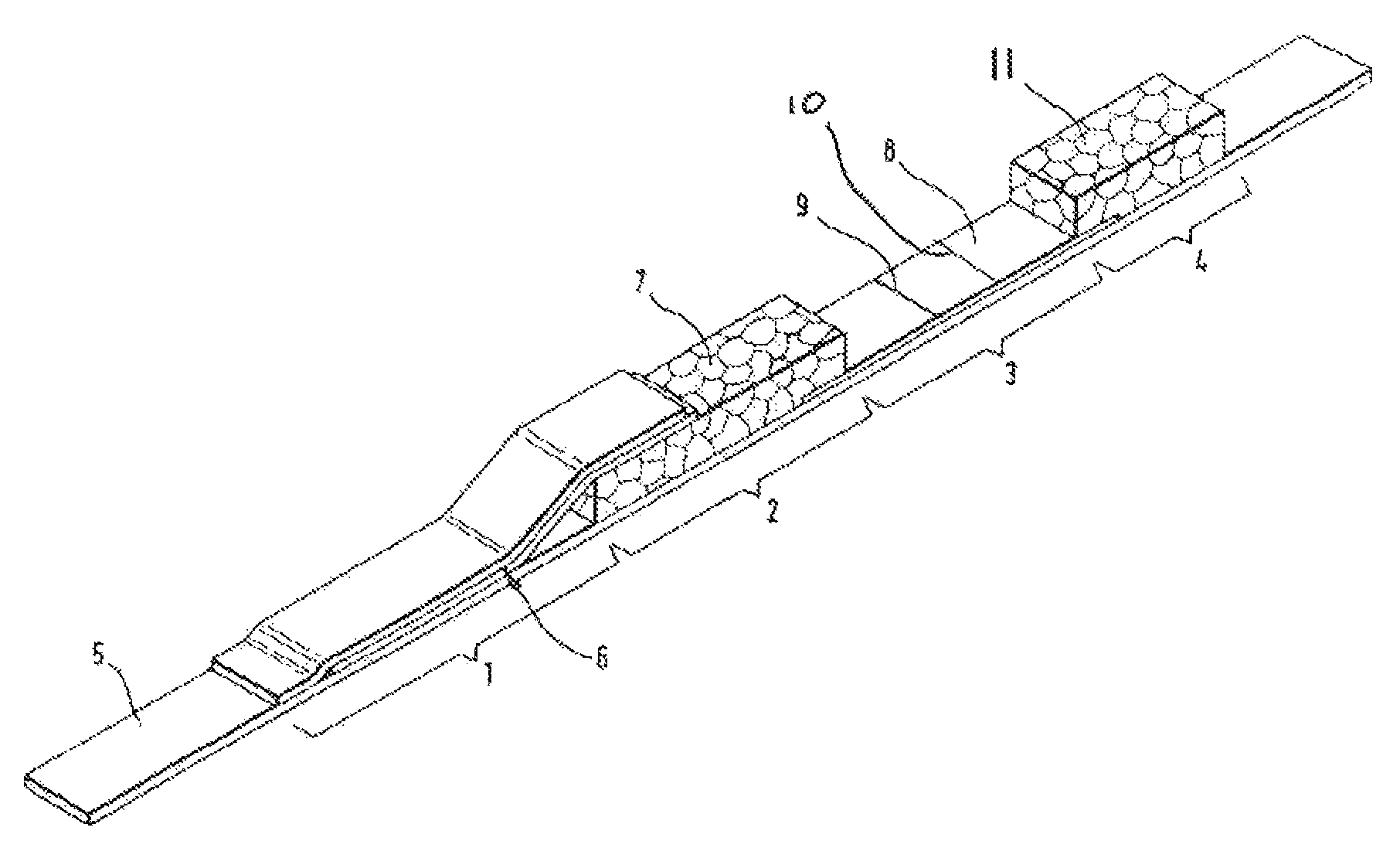
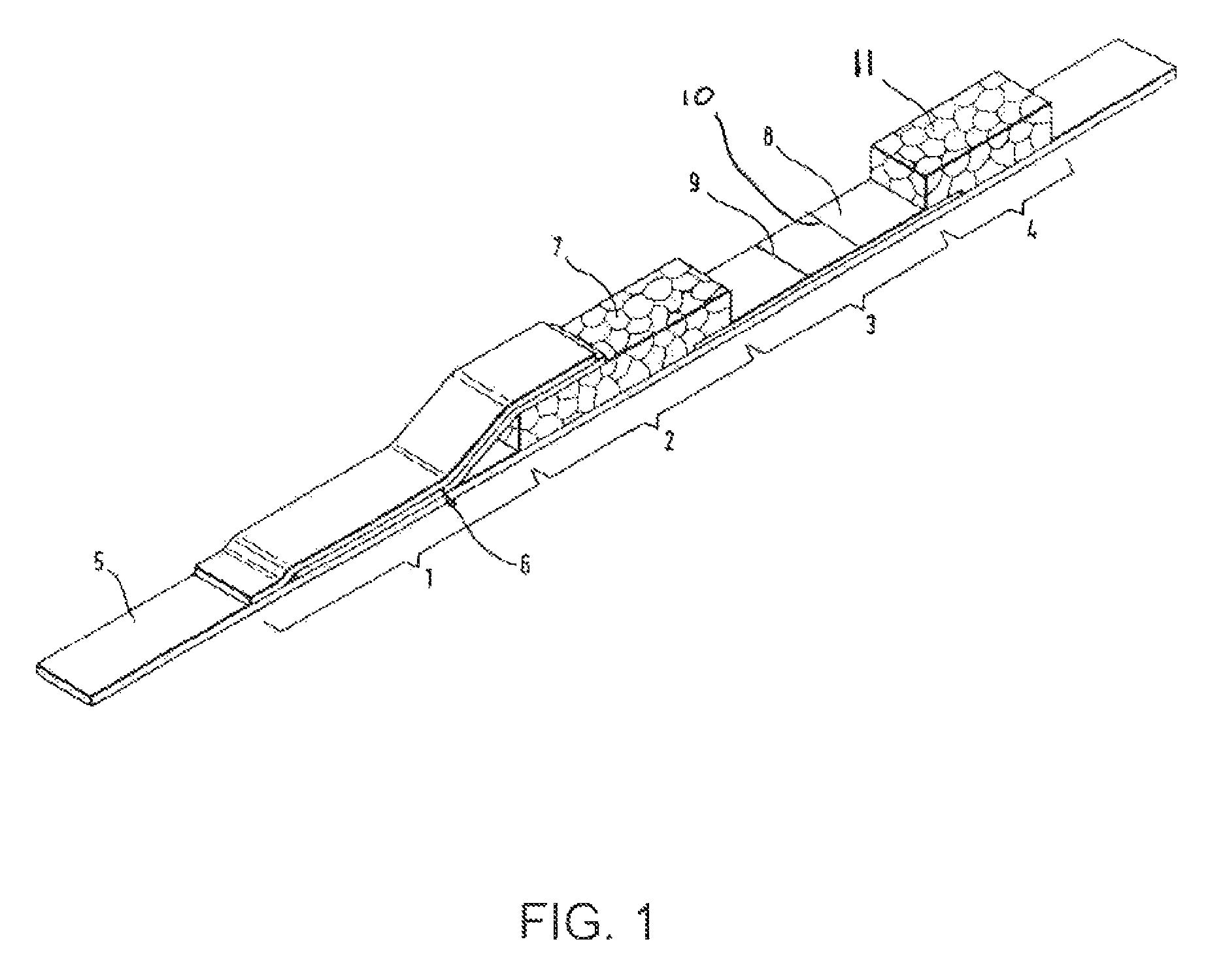
[0081]The test device (FIG. 1) consists of a support material (5) on which a sample application zone (1), an erythrocyte separation zone (2), a detection zone (3) and a suction zone (4) is applied. A sample application matrix (6) which partially overlaps the erythrocyte separation matrix (7) is disposed in the sample application zone (1). The erythrocyte separation matrix (7) in turn overlaps somewhat the detection matrix (8) (detection zone) on which polystreptavidin is immobilized in the form of a line (9) as a detection line and antigen or antigen analogue is immobilized for example as a synthetic or recombinant antigen peptide in the form of a line (10) as a control line. A suction matrix (11) overlaps somewhat the detection matrix (8). All those reagents are accommodated in the sample application matrix (6) which are required to form a complex with the analyte to be detected. In the present case t...


PUM

PropertyMeasurementUnit
thicknessaaaaaaaaaa
thicknessaaaaaaaaaa
thicknessaaaaaaaaaa

Abstract

The invention concerns a method for increasing the dynamic measuring range of especially immunological test elements in particular immunological chromatography test strips that can be evaluated optically that are based on specific binding reactions. The invention enables the dynamic measuring range of test elements based on specific binding reagents, especially of immunological test elements to be shifted towards higher analyte concentrations without impairing the lower detection limit. For this purpose it is proposed according to the invention that at least two zones are provided in or on the test element which contain reagents that generate detectable signals of different strengths due to different affinities for the analyte (for example in the case of antibodies that have different affinities for the analyte) or due to different principles of interaction with the analyte or with other reagents involved in the analyte detection (for example antibodies directed against the analyte in one zone and an analyte analogue in another zone). The signals in the at least two zones are used to evaluate the analyte concentration-signal strength relationship and are used to determine the analyte by means of a suitable method (correlation).

Description

BACKGROUND OF THE INVENTION[0001]The present invention relates generally to analytical test devices and, more particularly, to a method for increasing the dynamic measuring range of test elements based on specific binding reactions.[0002]Immunological test strips are a widespread device for the rapid determination of drugs, pregnancy hormones, infectious diseases or so-called “cardiac markers” such as troponin T. In this connection qualitative tests that are read by purely visual means and often only yield a “yes-no” answer as well as quantitative tests which are evaluated by means of a reading instrument are widely used.[0003]Rapid tests for immunologically detectable substances are known for numerous different parameters, for example from WO 97 / 06439, EP 0 291 194, U.S. Pat. Nos. 5,591,645, 4,861,711, 5,141,850, 6,506,612, 5,458,852, 5,073,484. In this case the immunological detection reagents (essentially labelled and unlabelled antibodies or antigens) are provided in a dry form ...

Claims


Application Information

Patent Timeline
Patent Type & Authority Patents(United States)
IPC IPC(8): G01N33/533G01N33/53G01N33/538G01N33/543
CPCG01N33/538G01N33/54386
Inventor BODENBACH, LUDGERSCHAEFFLER, JUERGENSPINKE, JUERGEN
Owner ROCHE DIAGNOSTICS OPERATIONS INC
Learn More