Op-R, a solid state filter

a solid-state filter and filter technology, applied in the field of electric filters, can solve the problems of compromising gain-bandwidth, difficult to achieve practical values on a monolithic chip, etc., and achieve the effects of low sensitivity, high gain-bandwidth, and low sensitivity

Inactive Publication Date: 2013-01-15
VOLPE GERALD THEODORE
View PDF7 Cites 3 Cited by
  • Summary
  • Abstract
  • Description
  • Claims
  • Application Information

AI Technical Summary

Benefits of technology

[0011]In classic active RC design the op-amp is chosen with sufficiently high gain-bandwidth through the filter's pass and transition bands. In this way the amplifier's phase shift does not enhance a filter stage's Q factor beyond the design limit (Q enhancement). The op-amp's gain-bandwidth is determined by its internal transistor cut-off frequencies but mainly limited by its internal compensation capacitor Cc. The compensation capacitor Cc is required with negative feedback applied due to excess phase shift from the stages of amplification. Otherwise, the amplifier oscillates. Thus, the compensation capacitor Cc is needed to make the op-amp work but compromises gain-bandwidth. In this way no external storage compensation elements are required. The specific method used does not compromise gain-bandwidth because it uses all of the devices' internal amplification potential in the filtering process. This advantage enables the design of wideband filters in the audio, video, and even UHF frequency ranges.
[0012]Another advantage of Op-R filters is that besides achieving filtering in a classic second order section-by-section approach, the Op-R method can also be extended to passive filter design. Since passive RLC filters enjoy low sensitivity compared to their active RC counterpart Op-R can likewise realize low sensitivity. Thus, with no L and C components required integrated circuit manufacturing is possible leading to compact reliable design.

Problems solved by technology

Their popularity stems from the convenient availability of operational amplifiers and the use of feedback lack to replace the inductor component L. Still the capacitor must be physically realized which presents difficulty in achieving practical values on a monolithic chip.
Thus, the compensation capacitor Cc is needed to make the op-amp work but compromises gain-bandwidth.

Method used


Image

  • Op-R, a solid state filter
  • Op-R, a solid state filter
  • Op-R, a solid state filter

Examples


Embodiment Construction

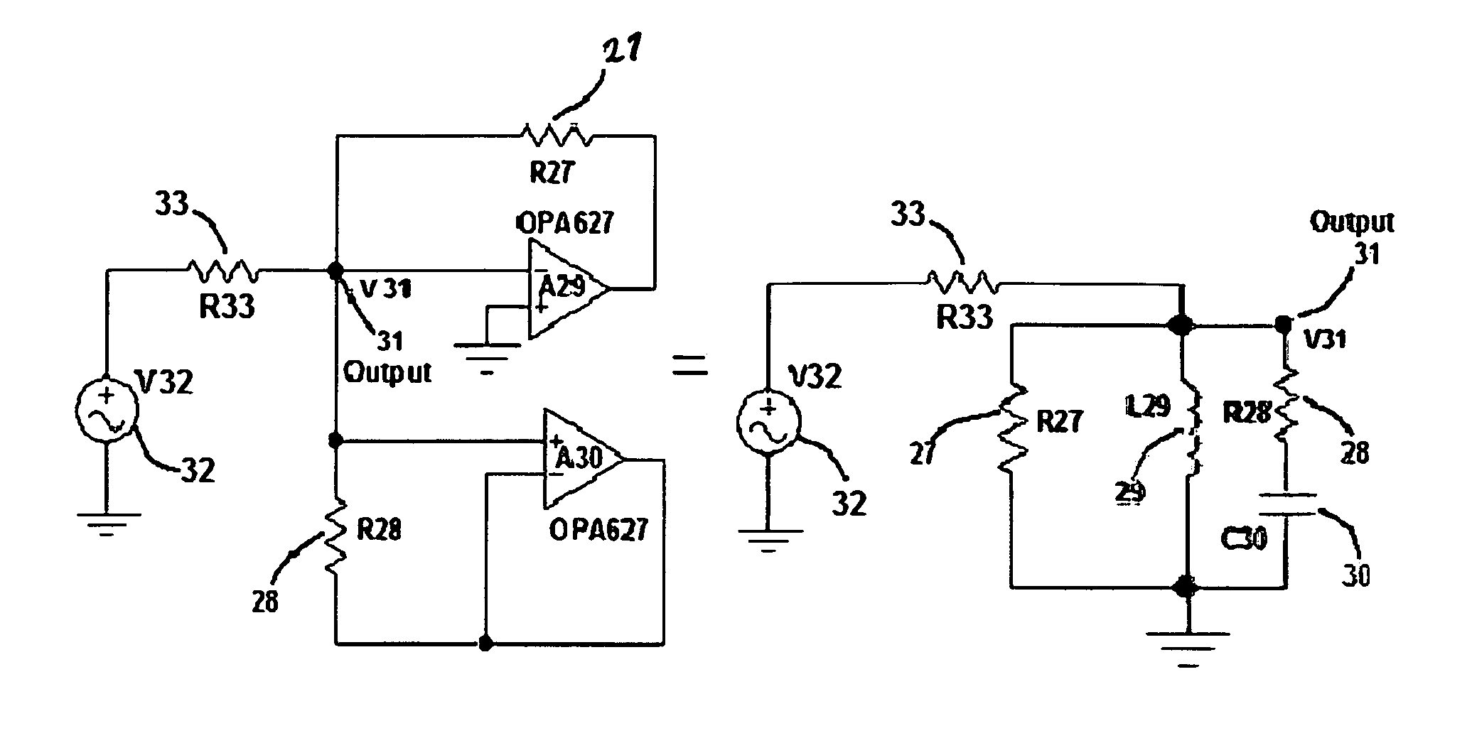
[0089]The present invention relates to a solid-state filter realized on a monolithic integrated circuit (IC). The IC is capable of physically realizing a broad class of filters over a wide frequency range. The filter class includes low pass, high pass, band pass, and band reject. The frequency range is either: audio, sub-audio, radio, video or HF, as well as UHF.

[0090]An object of the invention is to physically realize filters without the need of inductors or capacitors, and instead, utilizes operational amplifiers (op-amps) and resistors; hence the name OP-R.
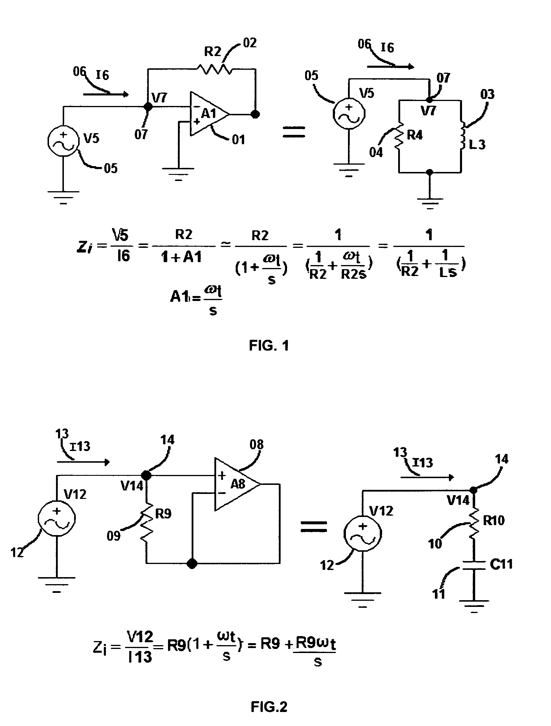
Basic Elements

[0091]Starting with the inductance element, FIG. 1 shows the equivalence of an OP-AMP 1 (A1) and an associated feedback RESISTOR 2 (R2) to a lossy inductor composed of INDUCTOR 3 (L3) and its associated parallel RESISTOR 4 (R4). Both equivalent circuits are driven by the same VOLTAGE SOURCE 5 (V5). Each circuit draws CURRENT 6 (I6) and has a responding VOLTAGE 7 (V7). The equivalence of the two circuits is given i...


PUM


Abstract

The device described herein proposes an electronic active filter void of capacitors and inductors. The circuit utilizes only operational amplifiers (Op-Amps) and resistors, hence the name Op-R. Although capable of being constructed of lumped circuit elements this filter is intended for integrated circuit (IC) applications. Filtering of signals can be accommodated sub-audio through the video frequency range depending on the selected op-amp ICs. Low pass, band pass, high pass, as well as ban reject frequency responses are achievable. Although the circuits described herein are single input-single output, multiple inputs and outputs present no difficulty, being limited only by chip space. Temperature and production spread variations are also considered within the realm of tenability.

Description

[0001]Reference Provisional Patent: U.S. 61 / 274,1783.BACKGROUND OF THE INVENTION[0002]1. Field of Invention[0003]The invention is directed toward electrical filters, and in particular to low power applications encountered in, for example, the fields of signal processing, communications, and noise reduction. The invention is directly applicable, but not limited to, integrated circuits.[0004]2. Prior Art[0005]Classically, electrical filters were constructed of lumped circuit passive elements. The elements included were resistors, inductors or coils, and capacitors, usually non-polarized. As electrical engineering evolved it became necessary to reduce the size and weight of these elements. Since the inductor represented the largest volume component there was motivation to remove it. It was later discovered that an amplifier with resistance-capacitance could replace the inductor to get the same effect.[0006]The new method was termed active RC filter design. Although active RC filters co...

Claims


Application Information

Patent Timeline
Patent Type & Authority Patents(United States)
IPC IPC(8): H03K5/00
CPCH03F3/45475H03H11/04H03H11/00H03F2203/45528
Inventor VOLPE, GERALD THEODORE
Owner VOLPE GERALD THEODORE
Why Eureka
Try Eureka