High-gain broadband directional element antenna with cavity reflector

A vibrator antenna and reflector technology, applied in the field of high-gain broadband directional vibrator antennas, can solve the problems of increasing the antenna volume and structural complexity, the electromagnetic wave gain is large, and the position of the reflector is invariable, etc., and achieves enhanced directional radiation characteristics, High gain, effect of increased gain bandwidth

Inactive Publication Date: 2019-09-10
BEIJING INSTITUTE OF TECHNOLOGYGY
View PDF1 Cites 3 Cited by
  • Summary
  • Abstract
  • Description
  • Claims
  • Application Information

AI Technical Summary

Problems solved by technology

However, the position of the reflector is not changeable, and the gain fluctuation will be large for electromagnetic waves of different frequencies
If the reflector is designed to be variable in position, it is necessary to increase the mechanical structure, increase the volume of the antenna and the complexity of the structure

Method used


Image

  • High-gain broadband directional element antenna with cavity reflector
  • High-gain broadband directional element antenna with cavity reflector
  • High-gain broadband directional element antenna with cavity reflector

Examples


Embodiment Construction

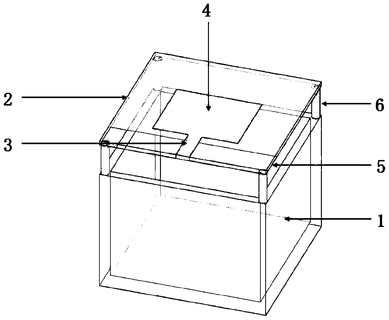
[0029] The invention provides a high-gain broadband directional dipole antenna with a cavity reflector. The basic idea is: add a cavity reflector under the omnidirectional broadband dipole antenna; the cavity reflector is a open-top container. In this scheme, the reflective object is changed from a flat plate to a cavity structure. The electromagnetic energy radiated from the omnidirectional antenna to the bottom of the antenna is reflected back by the cavity structure and the electromagnetic energy radiated to the top of the antenna can always produce the effect of in-phase superposition within a certain frequency band. This increases the gain bandwidth of the antenna and can achieve good gain flatness within a larger bandwidth.

[0030] This solution can use air as the medium. In practice, other substances can also be filled in the cavity as a medium, such as FR4 medium with a dielectric constant of 4.4, so that the size of the antenna can be reduced and the array arrangeme...


PUM


Abstract

The invention discloses a high-gain broadband directional element antenna with a cavity reflector. The high-gain broadband directional element antenna comprises an omni-directional element antenna anda cavity reflector, wherein the omni-directional element antenna is an omni-directional broadband element antenna or an omni-directional ultra-wideband element antenna; and the cavity reflector is located below the omni-directional element antenna, and the cavity reflector is an upper opening container made of a conductor. According to the scheme, a reflecting object is replaced from a flat plateinto a cavity structure, the electromagnetic energy radiated by the omni-directional antenna to the lower part of the antenna is reflected back by the cavity structure to always generate the same-phase superposition effect in a certain frequency band with the electromagnetic energy radiated to the upper part of the antenna, so that the gain bandwidth of the antenna is increased, and very high gain flatness in a relatively large bandwidth can be achieved.

Description

technical field [0001] The invention relates to the technical field of dipole antennas, in particular to a high-gain broadband directional dipole antenna with a cavity reflector. Background technique [0002] Microstrip antennas have the advantages of light weight, small size, low profile, low cost, and easy processing, and are currently widely used in communication radar and other fields. On the other hand, the impedance bandwidth of the microstrip antenna is narrow, and the impedance bandwidth of the ordinary microstrip antenna is only about 0.6%-3%, which cannot meet the needs of many communication radars. Therefore, it is very important to widen the impedance bandwidth of the microstrip antenna. significance. [0003] With the development of science and technology, UWB technology, as a wireless communication technology, has broad application prospects. At present, most UWB antennas are omnidirectional antennas, and have the characteristics of low gain and unstable patt...

Claims


Application Information

Patent Timeline
Patent Type & Authority Applications(China)
IPC IPC(8): H01Q19/10H01Q15/14H01Q1/38H01Q1/48H01Q1/50
CPCH01Q1/38H01Q1/48H01Q1/50H01Q15/14H01Q19/10
Inventor 李伟明葛良荣任武薛正辉鲍思慧
Owner BEIJING INSTITUTE OF TECHNOLOGYGY
Why Eureka
Try Eureka