
Travel time information system

a technology of information system and travel time, applied in the field of travel time information system, can solve the problems of frequent limited information conveyed by the optical output unit, and achieve the effects of preventing cramping, easy reading, and reducing computational effor

Active Publication Date: 2013-01-15
HARMAN BECKER AUTOMOTIVE SYST
View PDF10 Cites 98 Cited by
  • Summary
  • Abstract
  • Description
  • Claims
  • Application Information

AI Technical Summary

Benefits of technology

The invention is a device that can provide information on the time it takes to travel between different positions on an electronic map. This is done by a processor that looks at map data and determines the time it takes to travel through each position. The device can select which positions to include in the map and can adjust the travel times based on information from navigation systems. This helps to make the map easy to read and avoids unnecessary data clutter. The device can provide additional information related to travel times, making it easier to plan and navigate to different destinations.

Problems solved by technology

While navigation systems in which information is conveyed to a user, such as the driver of a vehicle, using an optical output unit, e.g., a display device, are known in the art, the information conveyed by the optical output unit is frequently fairly limited.

Method used


Image

  • Travel time information system
  • Travel time information system
  • Travel time information system

Examples


Embodiment Construction

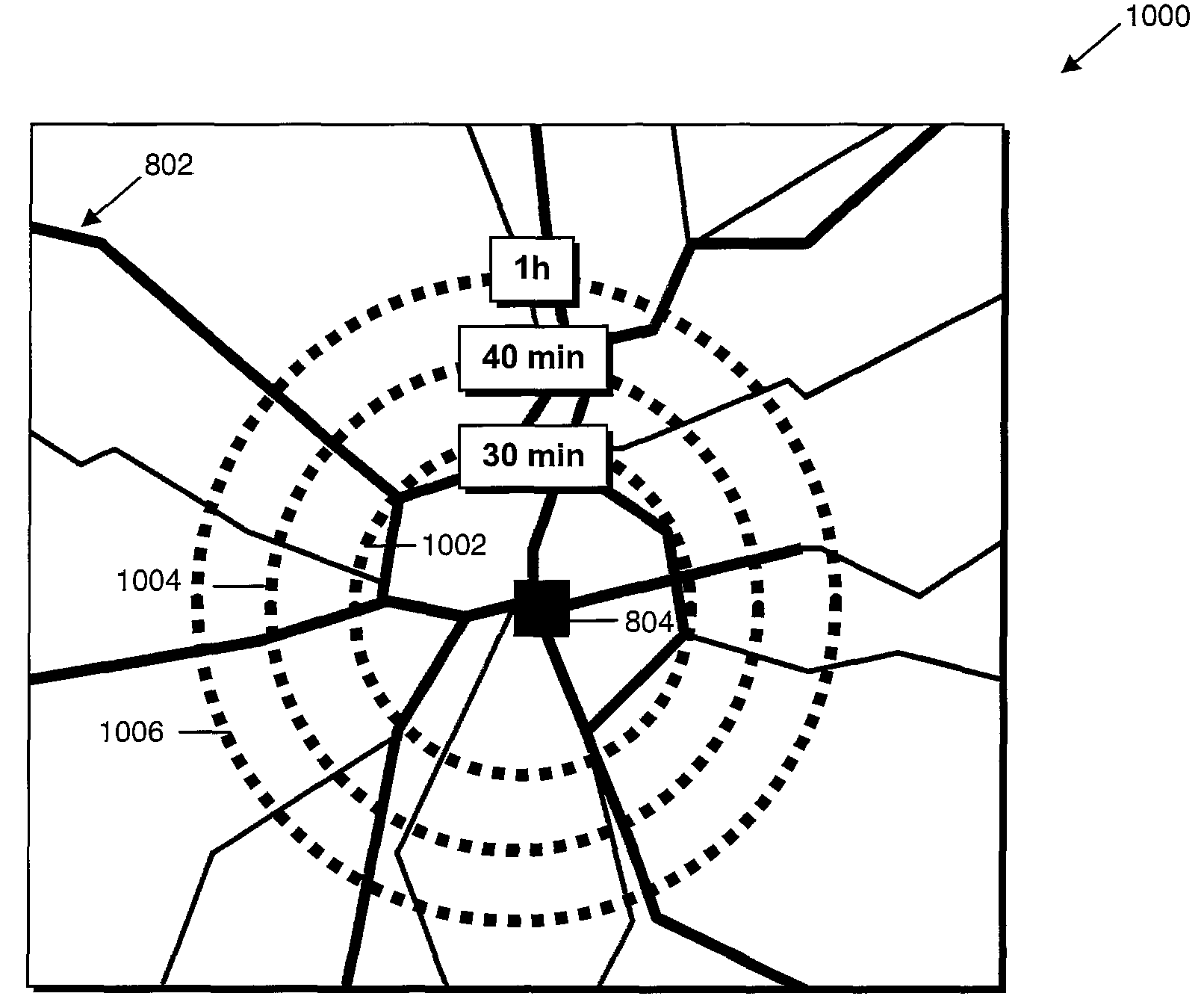
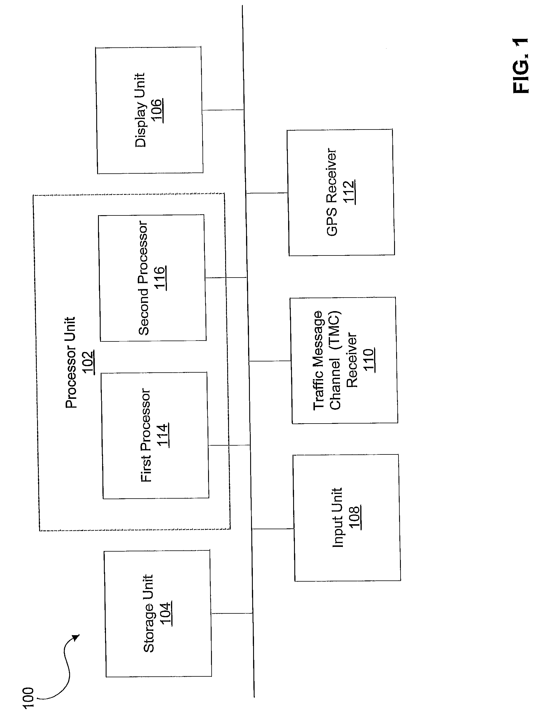
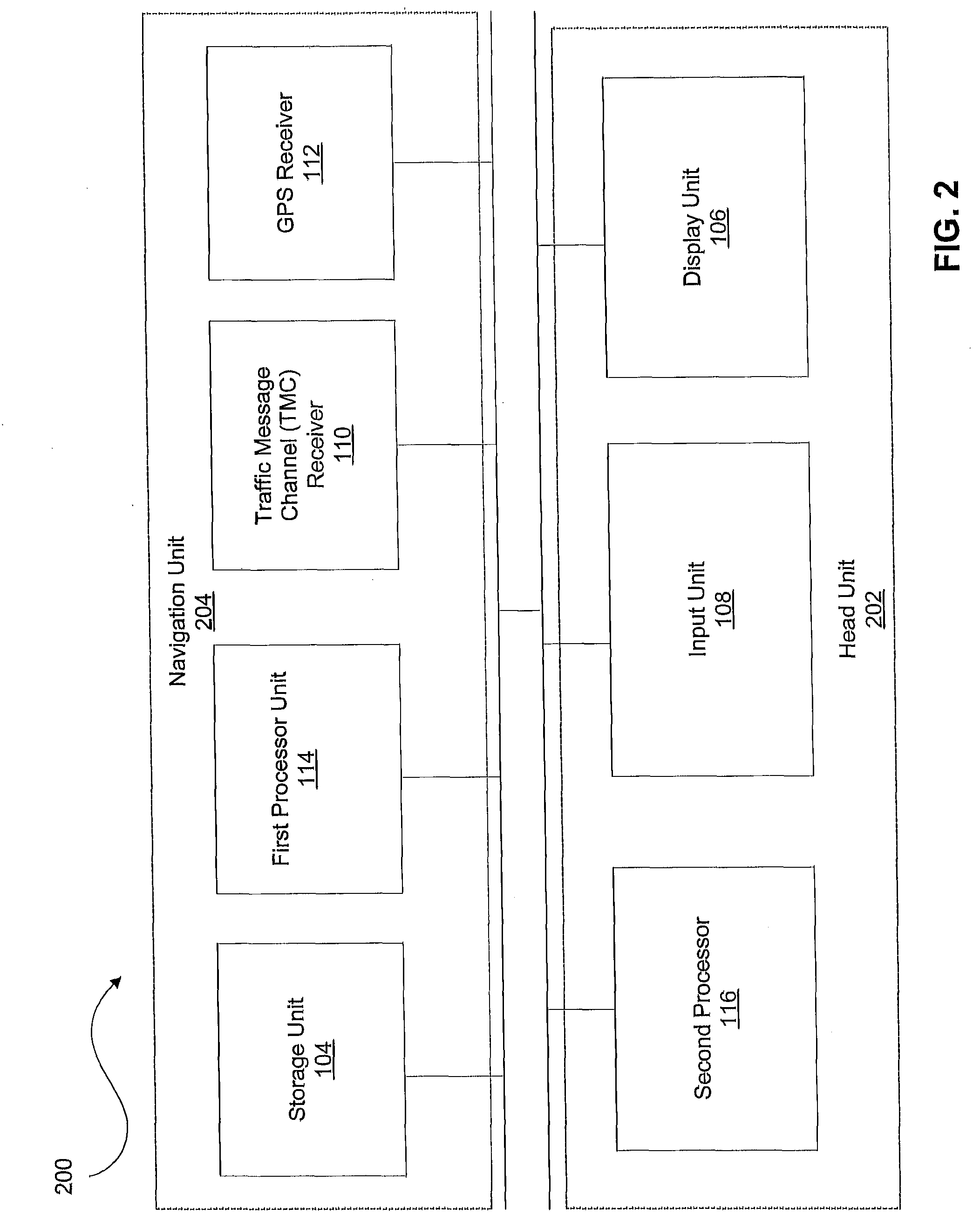
[0025]FIGS. 1-9 illustrate various examples of implementations of a system for providing travel time information. In particular, FIG. 1 illustrates one example of an implementation of a schematic block diagram of a device 100 for providing travel time information for a plurality of positions. The device 100 may include a processor unit 102, a storage unit 104, a display unit 106, an input unit 108, a traffic message channel (TMC)-receiver 110, and a GPS-receiver 112. All components are interconnected via a common bus.

[0026]The processor unit 102 performs two main functions, namely, (i) performing optimum route searches and (ii) selecting positions for which travel time information is to be displayed and determining the respective travel times for the selected positions. In the example illustrated in FIG. 1, the processor unit 102 includes a first processor 114 and a second processor 116 for performing these two different functions. For example, the first processor 114 may be configu...


PUM


Abstract

A system is provided for providing travel time information for a plurality of positions on an electronic map. The system provides map data including information on road segments, determines a plurality of road segment travel times based on the map data, selects a plurality of positions for which travel time information is to provided, determines a travel time for each of these positions in dependence on the road segment travel times, and displays an optical indicator for the travel times on an electronic map.

Description

RELATED APPLICATIONS[0001]This application claims priority of European Patent Application Serial Number 06 023 456.4, filed on Nov. 10, 2006, titled METHOD AND DEVICE FOR PROVIDING TRAVEL TIME INFORMATION, which application is incorporated in its entirety by reference in this application.BACKGROUND[0002]1. Field of the Invention[0003]The invention relates to a system for providing travel time information for a plurality of positions on an electronic map. In particular, the invention relates to methods and devices that allow travel time information to be selectively displaced for positions based on, e.g., selection criteria such as travel times or predefined positions, and which methods and devices may be employed in navigation systems aboard a vehicle.[0004]2. Related Art[0005]While navigation systems in which information is conveyed to a user, such as the driver of a vehicle, using an optical output unit, e.g., a display device, are known in the art, the information conveyed by the...

Claims


Application Information

Patent Timeline
Patent Type & Authority Patents(United States)
IPC IPC(8): G01C21/26
CPCG01C21/367G08G1/0969G01C21/3697G08G1/096716G08G1/09675G08G1/096775
Inventor WAGNER, THOMASWAGNER, OLIVER
Owner HARMAN BECKER AUTOMOTIVE SYST
Learn More