Retractable pontoon boat cover

a technology for retractable fabric covers and pontoon boats, which is applied in the direction of special-purpose vessels, vessel construction, transportation and packaging, etc. it can solve the problems of unsuitable for boating, lack of adequate support for attachable fabric in the front and rear of the structure, and the cover is difficult to lift, so as to improve the pivoting mechanism and eliminate the effect of unequal side-to-side movemen

Active Publication Date: 2013-01-29
HIGHFIELD JOHN
View PDF9 Cites 17 Cited by
  • Summary
  • Abstract
  • Description
  • Claims
  • Application Information

AI Technical Summary

Benefits of technology

[0011]The retractable pontoon boat cover of the present invention comprises an expanding frame system attached to both sides of the boat through a track apparatus fastened horizontally to the sides of the boat, for example along the edges of the deck. The frame system includes a plurality of U-shaped vertical support members designed to span the width of the boat, and to move fore and aft on the track. The vertical support members comprise vertical tube sections on the sides of the boat, each pair of vertical tube sections connected by an arched formation spanning the width of the boat. The U-shaped support members are interconnected with expanding scissors and sliding sleeves. The expanding scissors are placed between each vertical tube section on the port and starboard sides of the frame. The expanding scissors are attached to the bases (lower ends) of the vertical tube sections, oriented so the bottom portion of one side of a scissor is connected to the base of one vertical tube section and the bottom portion of the other side of the scissor is connected to the base of the adjacent vertical tube section. The tops of the expanding scissors are connected to sliding sleeves. The sliding sleeves are located midway on each vertical tube section and move in an up and down vertical motion when the expanding frame is extended or retracted. All standing vertical tube sections on both the port and starboard sides of the expanding frame system are connected in this fashion. The interconnection of the U-shaped vertical support members with the expanding scissor and sliding sleeve connection causes the frame system to move as a single unit when extended and retracted, and eliminates unequal side-to-side movement.
[0012]A further feature of the present invention is a U-shaped support constructed of two or more sections, which allows the expanding frame to extend and retract without binding if one side of the expanding frame advances at a faster rate than the other side.
[0013]Front and rear pivoting support sections are located in the front and rear of the expanding frame structure, comprising “angled” and “horizontal” U-shaped supports. The angled supports are located in-between the first (front) vertical support and the front horizontal support and the last (rear) vertical support and the rear horizontal support. These horizontal supports deploy to horizontal positions holding the cover fabric to the deck, and the angled supports deploy to an angled (e.g., 45-degree) fabric supporting position and interconnect the horizontal supports and the adjacent first and last vertical supports, by means of pivot structure located in the front and rear corners of the expanding frame structure. Springs extending between the vertical tube sections of the first and last vertical supports and the pivoting tube sections assist the pivoting motion during expansion and retraction of the expanding frame system.
[0014]To accomplish an improved pivot motion when the cover is expanded, and to latch the expanded cover in place, the front pivot section includes a front pivot arm cooperating with a front pivot guide. The front pivot arm is located at the base of the front side of the expanding frame system on each of the port and starboard sides. The front pivot arm is attached to the front pivot section and travels inside the track apparatus when the expanding frame is expanding or retracting. The front pivot guide is located at the front end of the track apparatus, when the expanding frame reaches full extension the front pivot arm engages the front pivot guide. The front pivot arm is guided to rotate down into the front pivot guide, and is latched in place by the deployment of the front angled support behind it, which allows for a more precise pivoting mechanism and also provides an efficient locking latch system. When the pivot arm is thus engaged with the pivot guide it prevents outside elements such as wind from lifting the front of the cover system.

Problems solved by technology

This unequal movement causes binding issues in the track apparatus.
The framework in my '472 patent also lacks adequate support for the attachable fabric in the front and rear of the structure, allowing water and other debris, i.e., leaves, branches etc. to collect between the first vertical support and the front stowing compartment, and between the last vertical support and the rear horizontal support.
The rear horizontal tube section in my '472 patent is unsecured when extended to support the fabric cover, and therefore is subject to wind causing this part of the cover to lift during heavy winds.
Another drawback of the retractable cover system in my '472 patent is the location of the cover's storage position.
This stowing compartment or box is costly and presents a number of problems.
Furthermore the bow storage location could incur damage as the bow contacts outside structures such as docks or other boats.

Method used


Image

  • Retractable pontoon boat cover
  • Retractable pontoon boat cover
  • Retractable pontoon boat cover

Examples


Embodiment Construction

[0030]Referring first to FIGS. 1 through 3, a retractable boat cover is shown in exemplary form in order to teach how to make and use the claimed invention.

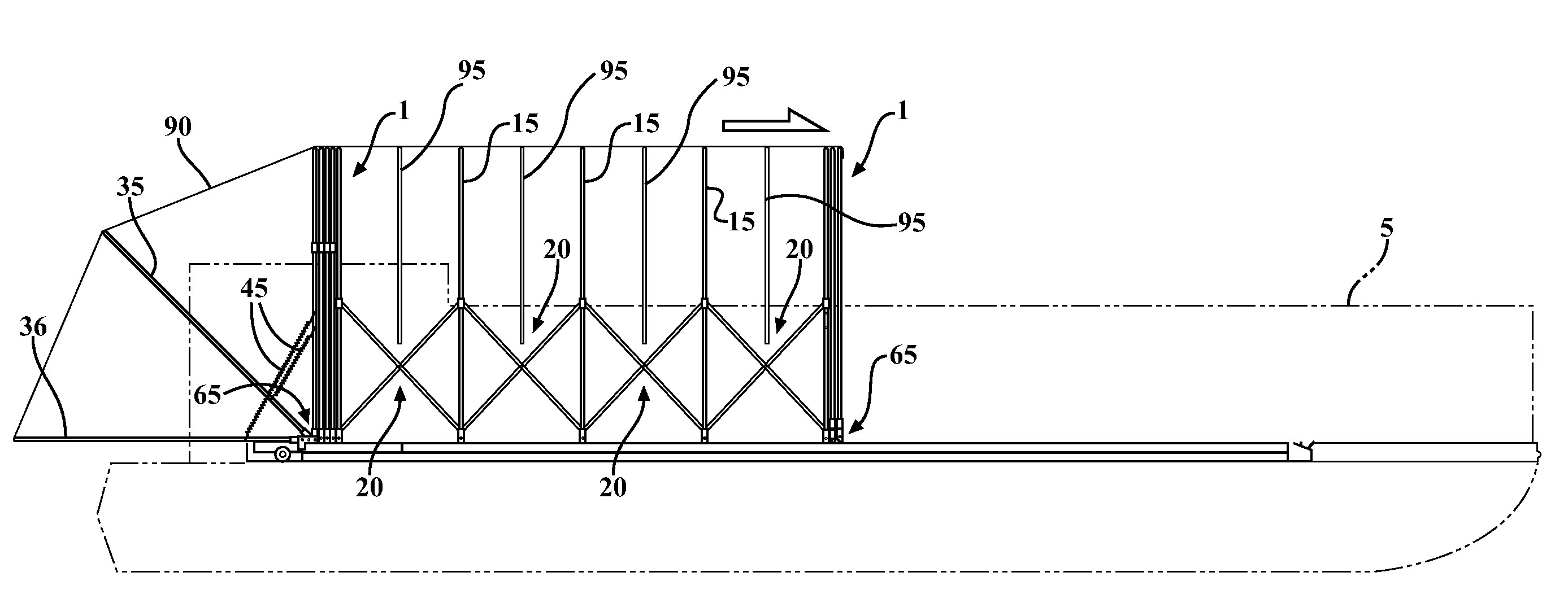
[0031]Looking at FIGS. 1-3, there is shown a typical pontoon boat (5) in outline schematic form. A cover system is provided that includes an expanding frame (1). The expanding frame (1) is designed to receive a flexible fabric cover (90) shown in outline in FIG. 2 and in further in cutaway in FIG. 3.

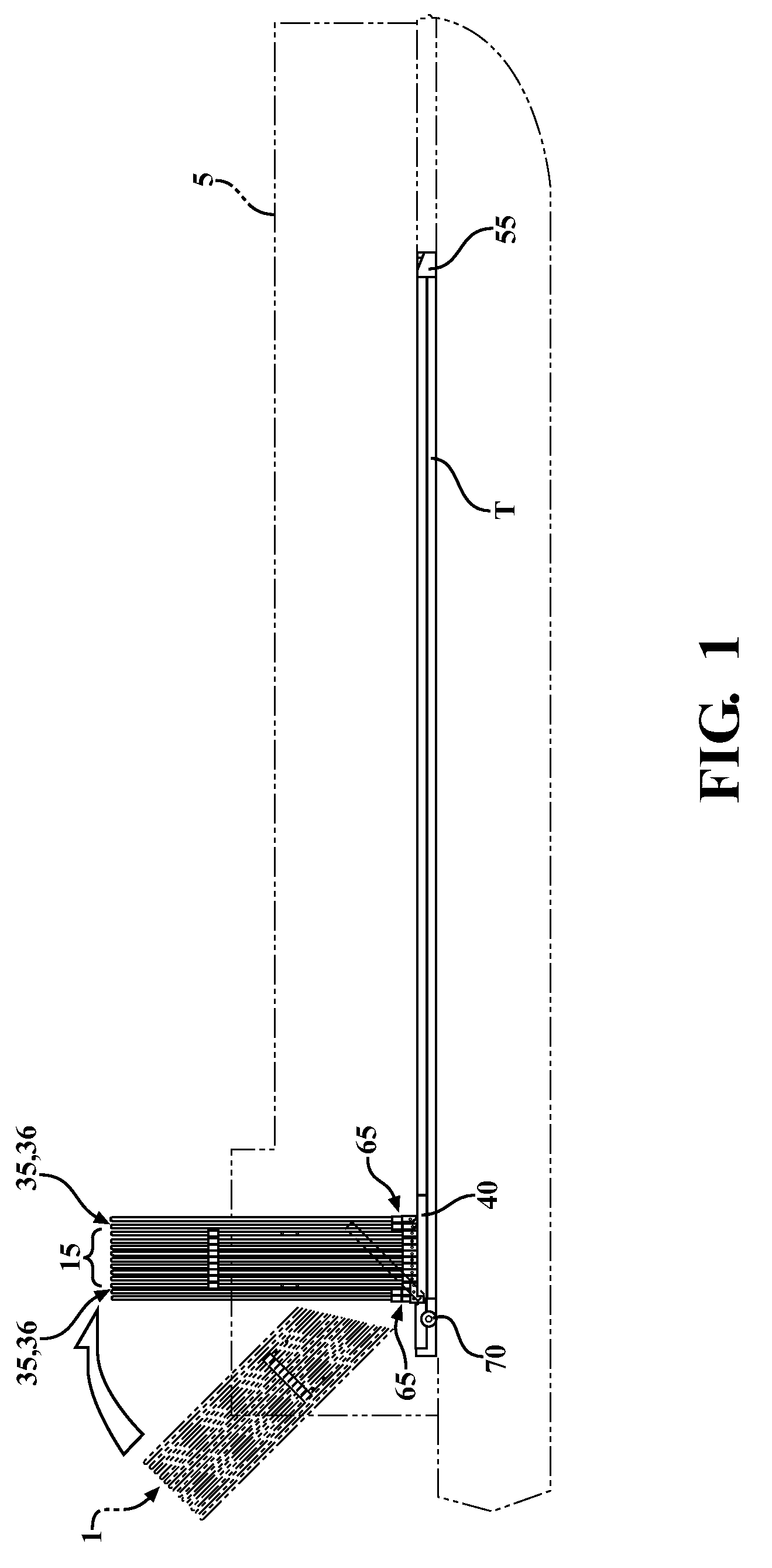
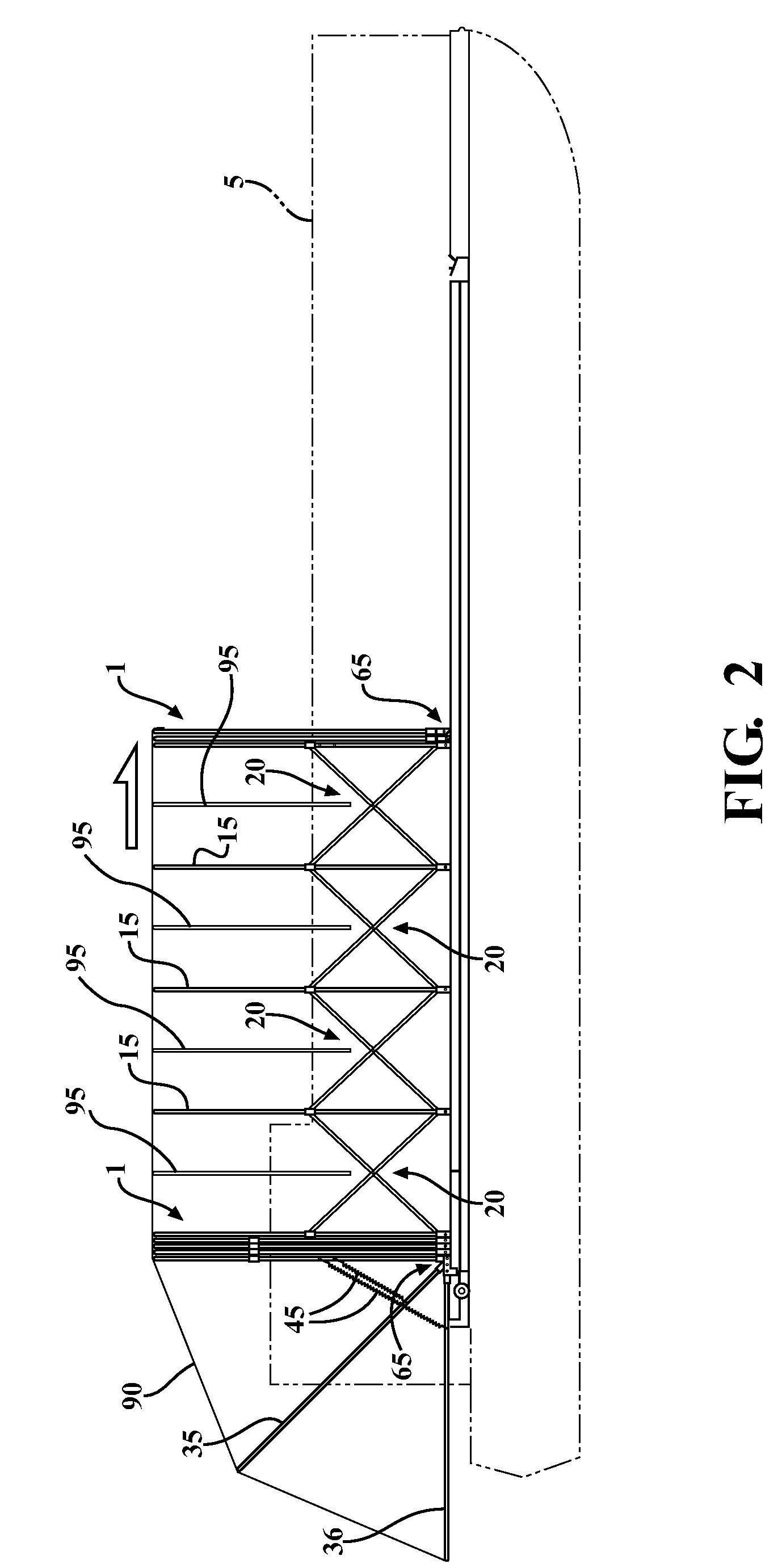
[0032]FIG. 1 shows the frame 1 in a fully-retracted position in solid lines, and in a storage position in which the fully-retracted frame 1 is tilted rearwardly at an approximately 45-degree angle. Frame 1 includes vertical supports (15) and front and rear pivot sections (65) including angle-deployed supports (35) and horizontally-deployed supports (36). FIG. 2 shows frame 1 partially extended along the length of the pontoon boat 5. FIG. 3 shows the fully-extended frame, with vertical support members (15) and the front and rear pivot ...


PUM


Abstract

A retractable cover system for a pontoon boat comprising an expanding frame of U-shaped supports sliding in tracks along the sides of the boat, the U-shaped supports interconnected by expanding scissors. The bow and stern ends of the frame are provided with pivoting sections that include horizontal and angled U-shaped supports to define fabric-supporting and fabric-securing structure at the bow and stern of the boat when the frame is fully extended. The retracted frame and fabric cover self-store at the stern of the boat by tilting a pivot station portion of the track rearwardly.

Description

RELATED APPLICATIONS / PRIORITY BENEFIT CLAIM[0001]None.FIELD[0002]The subject matter of the present application is in the field of retractable fabric covers for pontoon boats.BACKGROUND[0003]It is well known to provide a boat with a cover to prevent water and other debris from collecting inside the boat when the boat is not in use. A recent example is shown in my U.S. Pat. No. 7,484,472 B1. This particular cover is a manually-operated version of a retractable pontoon boat cover system. This cover system uses an expanding frame system to cover and uncover a pontoon boat. This frame system includes a plurality of U-shaped supports mounted to a device that causes directional movement, the device attachably fixed on the port and starboard sides of the boat's deck.[0004]The retractable cover in my '472 patent has a stowing compartment removably fixed to the bow of the boat, and the expanding frame system and attached fabric cover pivots into and out of the storage compartment.[0005]I have...

Claims


Application Information

Patent Timeline
Patent Type & Authority Patents(United States)
IPC IPC(8): B63B17/00
CPCB63B19/18B63B19/19
Inventor HIGHFIELD, JOHN
Owner HIGHFIELD JOHN
Why Eureka
Try Eureka