
Manual inflator with cylinder connector and status indicator

a status indicator and inflator technology, applied in the field of inflators, can solve the problems of inability to properly operate, inflators that have been improperly serviced, and devices intended for emergency situations are often stored away

Active Publication Date: 2013-01-29
HALKEY ROBERTS CORP
View PDF26 Cites 16 Cited by
  • Summary
  • Abstract
  • Description
  • Claims
  • Application Information

AI Technical Summary

Problems solved by technology

Unfortunately, devices intended to be used during emergency situations are often stored away, such as in a locker, hold, or well of a boat, and ignored for inordinate periods of time.
Further, when eventually removed from storage for maintenance, such emergency devices are commonly inspected and serviced only by yachtsmen and boaters who lack any specialized training or expertise in servicing inflators.
Consequently, inflators may be improperly serviced by inadvertently installing a spent gas cylinder or in the case of an automatic inflator, by inadvertently installing a spent bobbin.
Obviously, an inflator that has been improperly serviced, will fail to properly operate during an emergency situation.
However, it is incapable of indicating the charged condition of the gas cylinder.
In such scenarios, it is possible for the yachtsman or boater to visualize only the “green” indication and carelessly fail to recognize the “red” indication.

Method used


Image

  • Manual inflator with cylinder connector and status indicator
  • Manual inflator with cylinder connector and status indicator
  • Manual inflator with cylinder connector and status indicator

Examples


Embodiment Construction

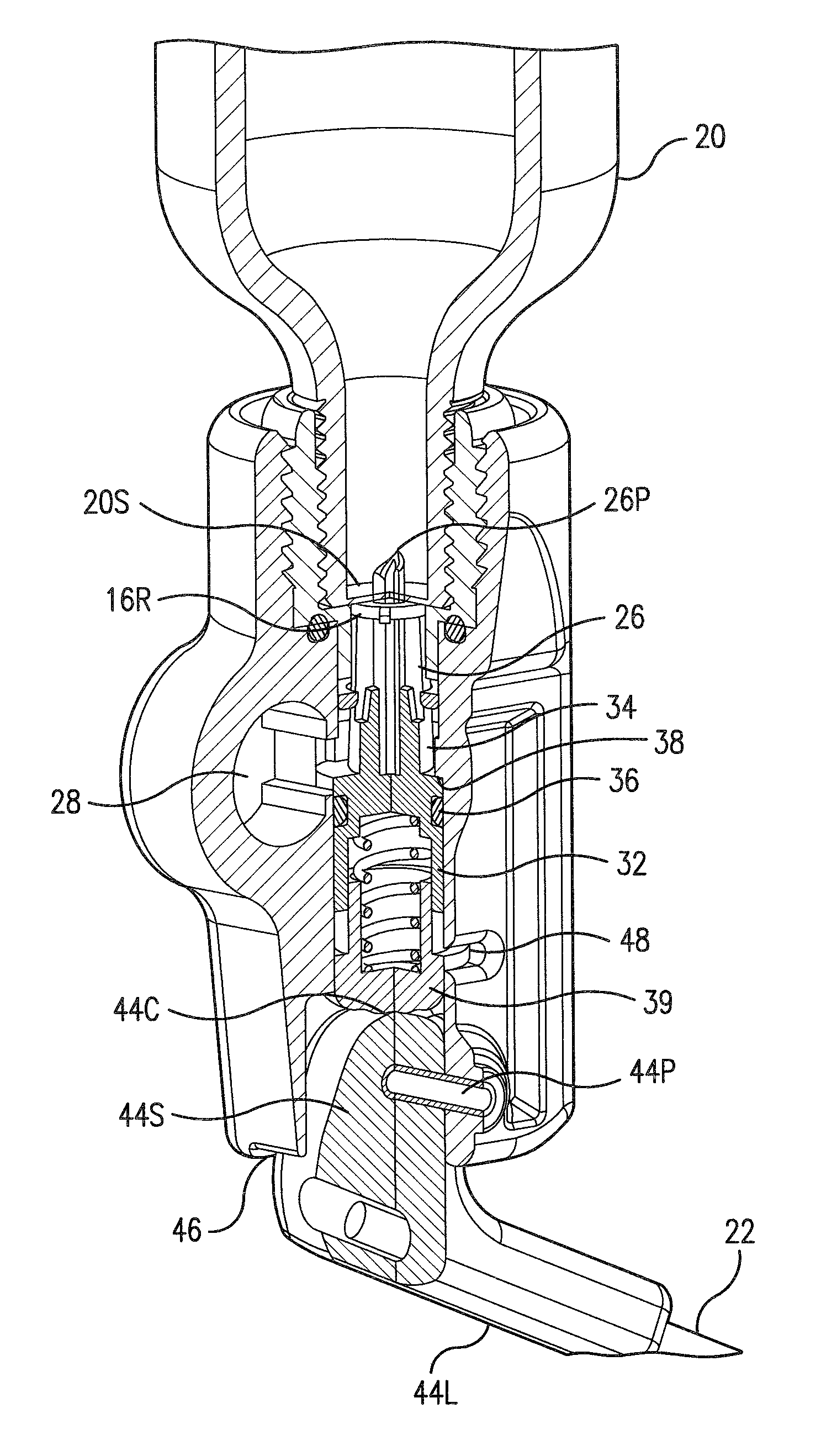
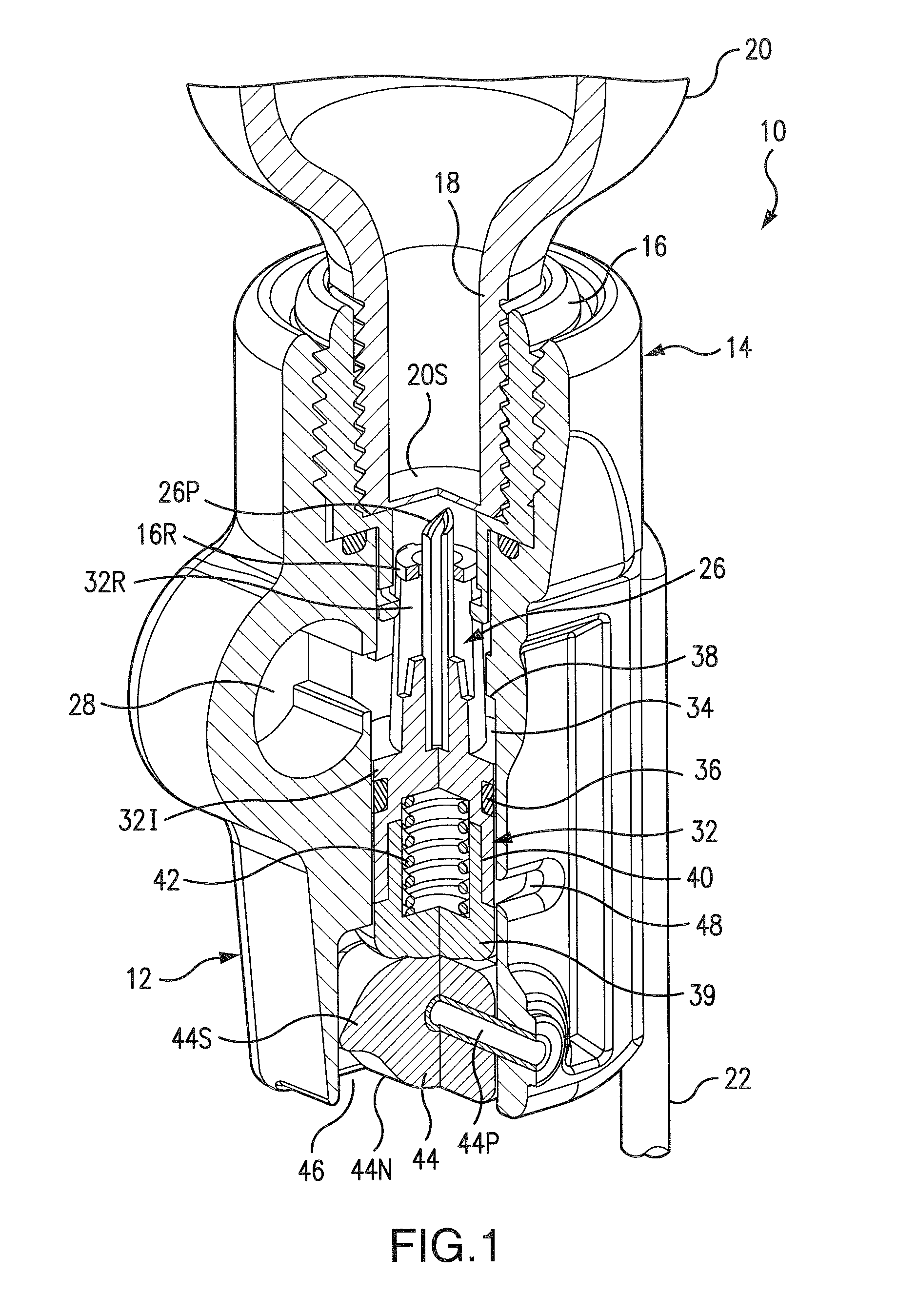
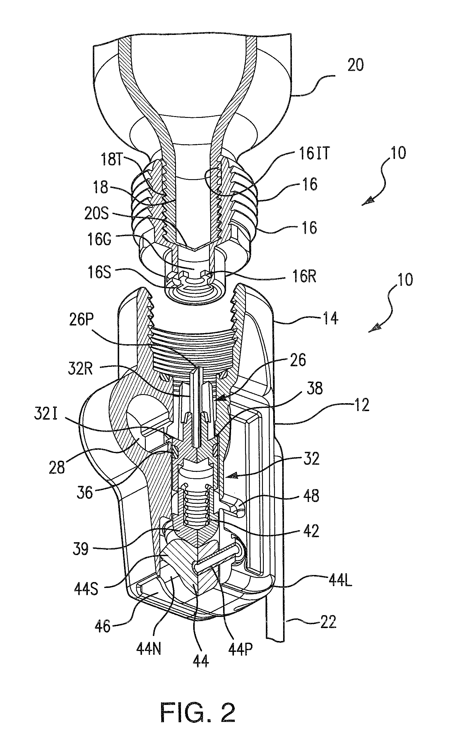
[0031]Referring to FIG. 1, the manual inflator 10 of the invention comprises a generally rectangular body 12 having a generally circular-cylindrical boss 14 with internal threads. A generally circular-cylindrical threaded collar 16 is permanently threadably connected onto the threaded neck 18 of a conventional gas cylinder 20. The collar 16 serves as a connector to threadably connect the gas cylinder 20 to the inflator 10 (and to prevent replacement use of other gas cylinders without such collars 16).

[0032]As described below, a lanyard 22 with a jerk handle 24 is operatively connected to a pierce pin assembly 26 reciprocably contained within the rectangular body 12 to pierce the frangible seal 20S of the gas cylinder 20 whereupon the escaping gas from the gas cylinder 20 flows out a conventional manifold 28 sealingly connected to the inflatable device to which the inflator 10 is installed, thereby inflating the device.

[0033]Referring to FIGS. 2 and 2A, the generally circular-cylindr...


PUM


Abstract

A manual inflator having a status indicator that indicates whether a fully-charged, unspent gas cylinder has been installed on the inflator. The status indicator comprises a “single point” indicator having an indicator window that displays the color “green” when the automatic inflator is fully operational or the color “red” when the inflator is at least partially inoperable automatically due to the removal of the gas cylinder or due to the firing of the inflator resulting in a spent gas cylinder.

Description

CROSS-REFERENCE TO RELATED APPLICATIONS[0001]This application claims the benefit of provisional patent applications Ser. Nos. 61 / 226,131 filed Jul. 16, 2009 and 61 / 169,713 filed Apr. 15, 2009, the disclosures of which are hereby incorporated by reference herein.BACKGROUND OF THE INVENTION[0002]1. Field of the Invention[0003]This invention relates to inflators for inflating articles such as life rafts, life vests, and the like. More particularly, this invention relates to inflators having indicators that indicate the operating condition of the inflator.[0004]2. Description of the Background Art[0005]Presently, there exist many types of inflators designed to inflate inflatable articles such as personal floatation devices (life vests, rings and horseshoes), life rafts, buoys and emergency signaling equipment. Inflators typically comprise a body for receiving the neck of a cylinder of compressed gas such as carbon dioxide. A reciprocating pierce pin is disposed within the body of the in...

Claims


Application Information

Patent Timeline
Patent Type & Authority Patents(United States)
IPC IPC(8): B67D7/00B67D7/22F16K15/20B63C9/125B63C9/19F16K33/00B63C9/15
CPCB63C9/19B63C9/18Y10T137/0318Y10T137/1684Y10T137/3662Y10T137/6123Y10T137/8359
Inventor ROGIER, STEPHEN J.FAWCETT, JR., LYMAN W.KING, ALAN D.
Owner HALKEY ROBERTS CORP
Learn More