Mounting apparatus for a vibration-sensitive module

a technology of vibration-sensitive modules and mounting apparatuses, which is applied in the direction of mechanical apparatus, machine supports, shock absorbers, etc., can solve the problems of degrading the performance of the module or rendering it inoperable, vibrational force impulses that are rarely unidirectional in nature, and are often incapable of adequately isolating, so as to reduce the cross-coupling of vibrational force impulses

Active Publication Date: 2013-01-29
DELPHI TECH IP LTD
View PDF7 Cites 6 Cited by
  • Summary
  • Abstract
  • Description
  • Claims
  • Application Information

AI Technical Summary

Benefits of technology

[0006]The present invention is directed to an improved vibration isolating mounting apparatus for vibration-sensitive module having a mounting flange sandwiched between axial faces of upper and lower elastomeric bushings that are secured to a vibrational base, where the mounting flange has cammed surfaces radially adjacent to the bushings that variably engages an outer radial periphery of the bushings in response to vibrational movement of the base. The cammed surfaces produce a desired force vs. deflection characteristic of the mounting apparatus, and the bushing material retains its compressibility under load to minimize cross-coupling of vibrational force impulses.

Problems solved by technology

If too much vibrational energy is transmitted to the module, electronic components and solder joints in the module can suffer fatigue failures that degrade the performance of the module or render it inoperative.
Of course vibrational force impulses are rarely unidirectional in nature, and the bushing assembly 14 is frequently incapable of adequately isolating module 12 in the transverse plane.

Method used


Image

  • Mounting apparatus for a vibration-sensitive module
  • Mounting apparatus for a vibration-sensitive module
  • Mounting apparatus for a vibration-sensitive module

Examples


Embodiment Construction

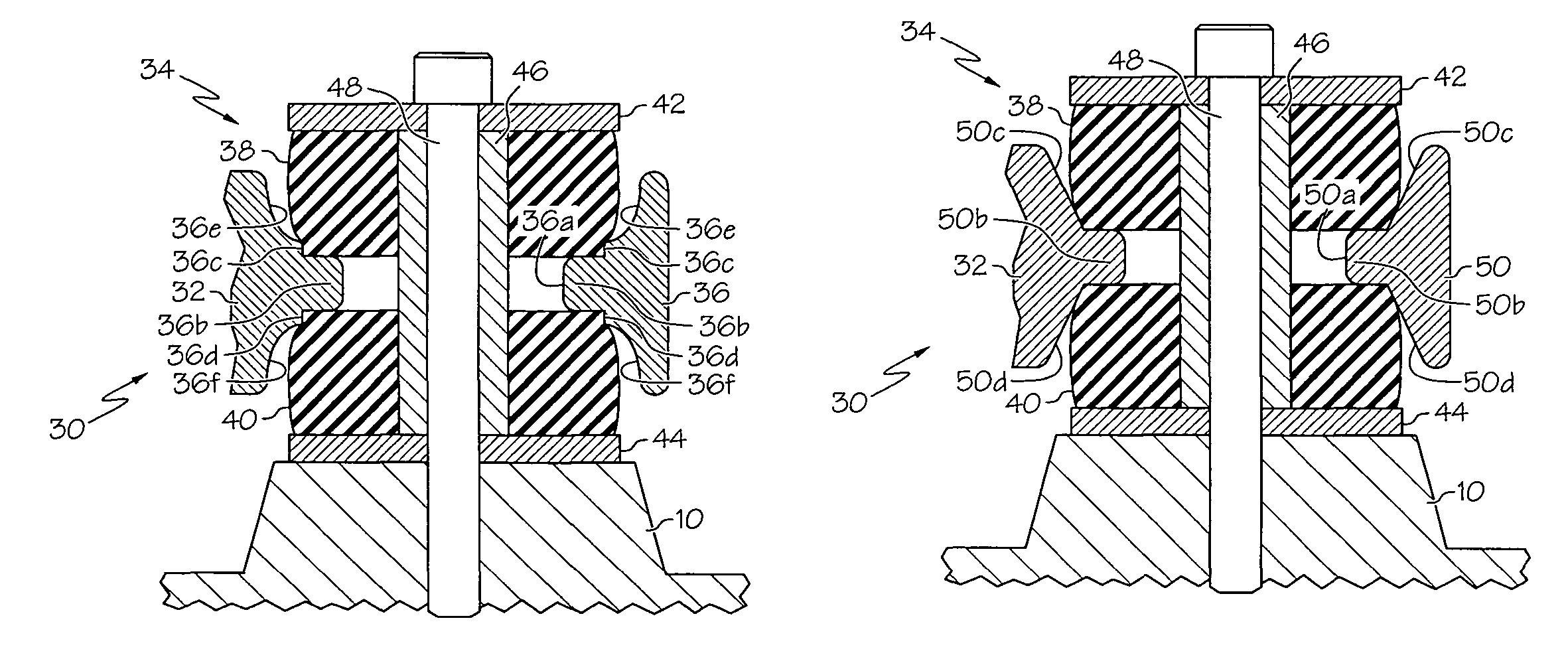
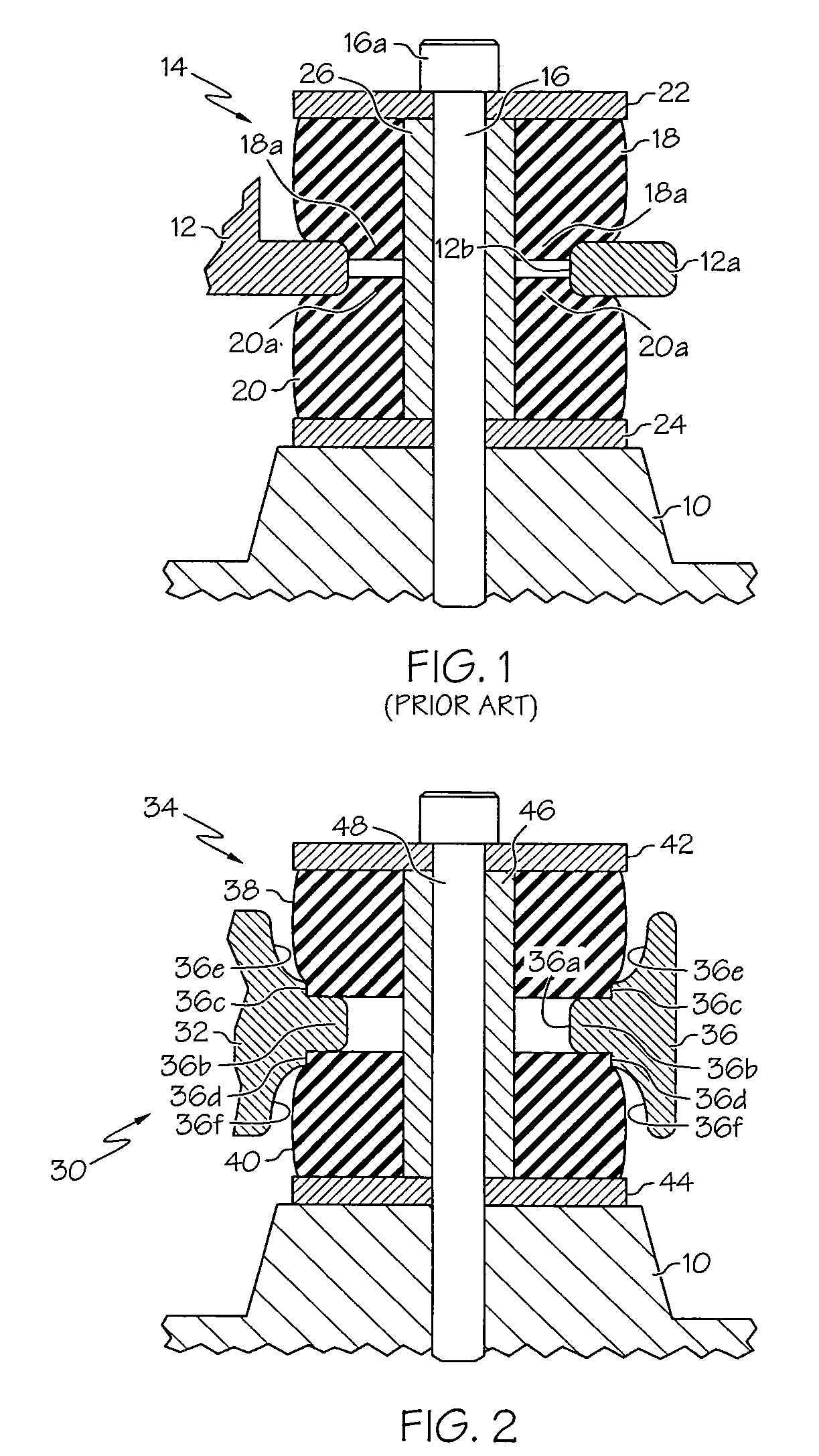
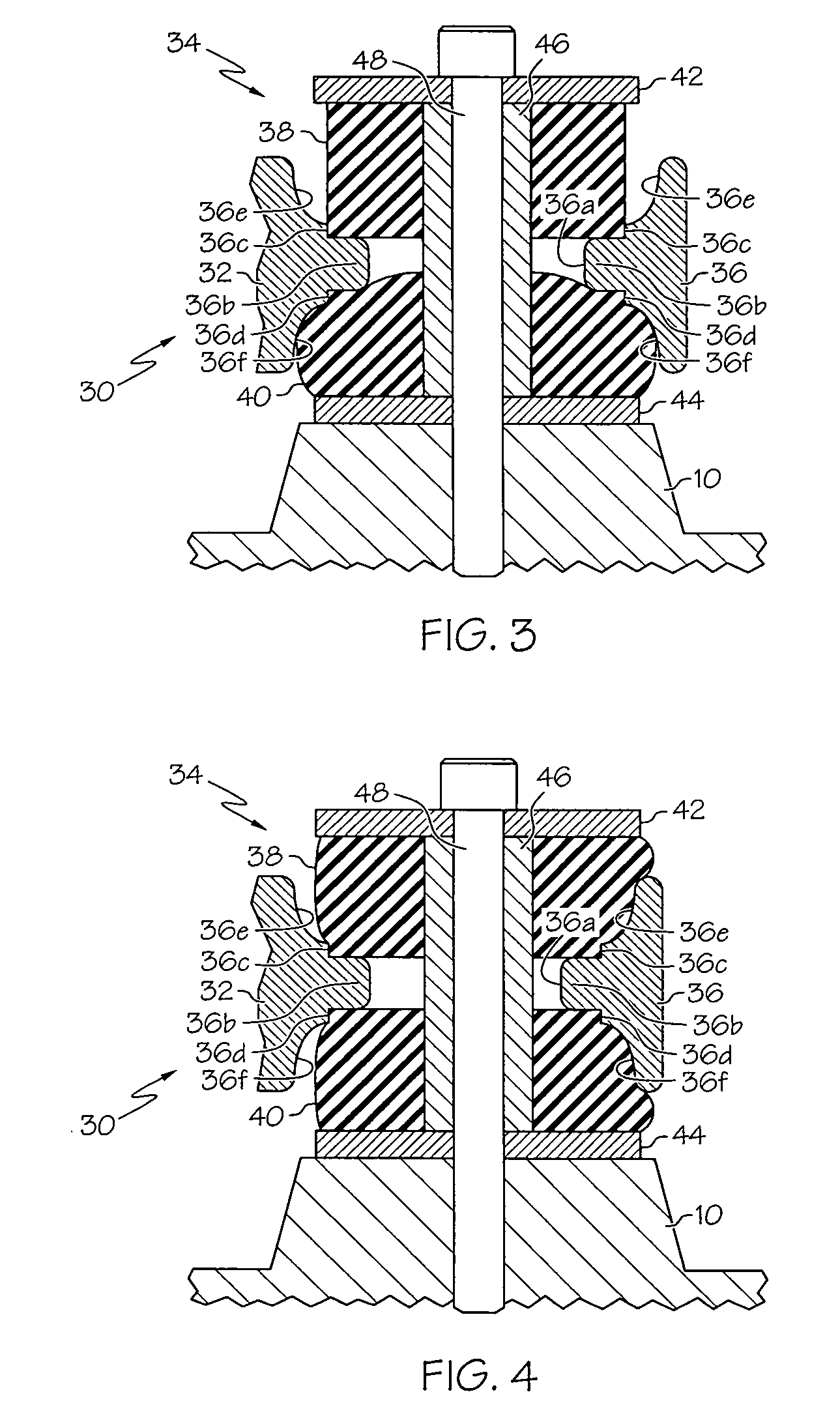
[0012]Referring to FIG. 2, the reference numeral 30 generally designates a mounting apparatus for a vibration-sensitive module 32 according to this invention. The mounting apparatus 30 includes a mostly conventional bushing assembly 34 and a unique module flange 36 having an internal through-hole 36a. Similar to the prior art bushing assembly 14 of FIG. 1, the bushing assembly 34 includes upper and lower annular elastomeric bushings 38 and 40, upper and lower washers 42 and 44, and a tubular sleeve 46 surrounding a mounting bolt 48. The bolt 48, washers 42 and 44, and sleeve 46 are identical to the prior art mounting apparatus depicted in FIG. 1. However, the upper and lower bushings 38 and 40 are not undercut as in the prior art bushing assembly 14. Instead, the bushings 38 and 40 are purely cylindrical in profile, and rest against the annulus 36b of flange 36 bordering through-hole 36a, leaving the core of annulus 36b free of elastomeric material. Preferably, the flange 36 has a p...


PUM


Abstract

A vibration-sensitive module having a mounting flange is mounted to a vibrational base with a bushing assembly secured to the base, where the mounting flange has cammed surfaces radially adjacent to the bushing assembly that variably engage the radial peripheries of the bushings in response to vibrational movement of the base. The cammed surfaces produce a desired force vs. deflection characteristic of the mounting apparatus, and the bushing material retains its compressibility under load to minimize cross-coupling of vibrational force impulses.

Description

TECHNICAL FIELD[0001]The present invention relates to apparatus for mounting a vibration-sensitive module on a vibrational base such as an internal combustion engine, and more particularly to a mounting geometry that more effectively isolates the module from vibrational movements of the base.BACKGROUND OF THE INVENTION[0002]When a vibration-sensitive module such as an electronic control unit is mounted on a vibrational base such as an internal combustion engine, elastomeric bushings are interposed between the module and the base to dampen the amount of vibrational energy transmitted from the base to the module. If too much vibrational energy is transmitted to the module, electronic components and solder joints in the module can suffer fatigue failures that degrade the performance of the module or render it inoperative.[0003]FIG. 1 depicts a prior art arrangement for mounting an electronic module on a vibrational base 10. The module housing 12 is typically a cast or stamped metal par...

Claims


Application Information

Patent Timeline
Patent Type & Authority Patents(United States)
IPC IPC(8): F16F3/00
CPCF16F3/0876
Inventor STILLABOWER, MORRIS D.
Owner DELPHI TECH IP LTD
Why Eureka
Try Eureka