Implantable sensor electrodes and electronic circuitry

a sensor electrode and electronic circuit technology, applied in the field of sensor electronics, can solve the problems of increasing the burden on associated electronics used to obtain and process signals received from such sensors, compromising the integrity of measurements being made with the electrodes, and increasing the burden on electrodes used in conjunction with biomolecules, so as to achieve the effect of minimizing cross coupling

Active Publication Date: 2009-04-28
MEDTRONIC MIMIMED INC
View PDF78 Cites 184 Cited by
  • Summary
  • Abstract
  • Description
  • Claims
  • Application Information

AI Technical Summary

Benefits of technology

[0011]The first electrode may wrap around the second electrode in a U-shaped fashion or may surround three sides of the second electrode. The layout of the first electrode and a second electrode may be such that it minimizes cross coupling between the first electrode and the second electrode.

Problems solved by technology

The development of sensors that can survive for extended periods in less than ideal environments has increased the burden on associated electronics used to obtain and process signals received from such sensors.
In addition, the availability of physiological parameter sensors that may be placed in a vascular environment or other environment that may subject a physiological parameter sensor to constant fluid environments has increased the burden on electrodes used in conjunction with a biomolecule that may be part of the physiological parameter sensor.
Because multiple electrodes may be used in physiological parameter sensing applications, fluids such as, for example, blood, may create multiple conductive paths across electrodes that compromise the integrity of measurements being made with the electrodes.
Electrode configuration and associated circuitry known up to this point have been ill-equipped to handle the demands of such an environment.
Moreover, the extended periods of time in which a physiological parameter sensor may be implanted in vivo have placed extra demands on the power sources driving the sensor electrodes and sensor electronics.
However, with the advent of sensors for long term in vivo implantation, storing a sensor with an activated power source may deplete the power source to such an extent that using the sensor for long term in vivo implantation may be impractical and even unadvisable.

Method used


Image

  • Implantable sensor electrodes and electronic circuitry
  • Implantable sensor electrodes and electronic circuitry
  • Implantable sensor electrodes and electronic circuitry

Examples


Embodiment Construction

[0026]In the following description of preferred embodiments, reference is made to the accompanying drawings which form a part hereof, and in which are shown by way of illustration specific embodiments in which the invention may be practiced. It is to be understood that other embodiments may be utilized and structural changes may be made without departing from the scope of the preferred embodiments of the present invention.

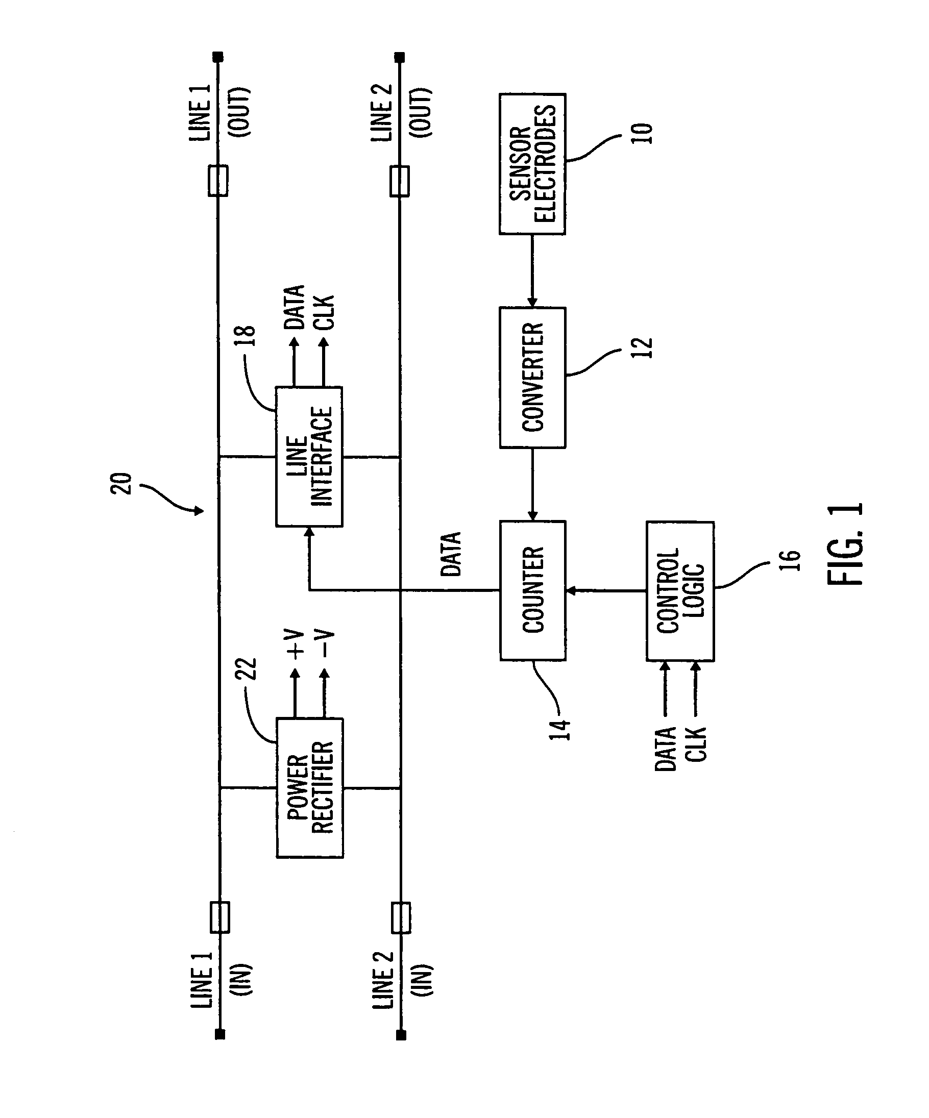
[0027]FIG. 1 shows a general block diagram of an electronic circuit for sensing an output of a sensor according to an embodiment of the present invention. At least one pair of sensor electrodes 10 may interface to a data converter 12, the output of which may interface to a counter 14. The counter 14 may be controlled by control logic 16. The output of the counter 14 may connect to a line interface 18. The line interface 18 may be connected to input and output lines 20 and may also connect to the control logic 16. The input and output lines 20 may also be connected ...


PUM

PropertyMeasurementUnit
voltageaaaaaaaaaa
current-voltage curveaaaaaaaaaa
voltagesaaaaaaaaaa

Abstract

An electronic circuit for sensing an output of a sensor having at least one electrode pair and circuitry for obtaining and processing the sensor output. The electrode pair may be laid out such that one electrode is wrapped around the other electrode in a U-shaped fashion. The electronic circuitry may include, among other things, a line interface for interfacing with input / output lines, a rectifier in parallel with the line interface, a counter connected to the line interface and a data converter connected to the counter and the electrode pair. The data converter may be a current-to-frequency converter. In addition, the rectifier may derive power for the electronic circuit from communication pulses received on the input / output lines.

Description

CROSS-REFERENCE TO RELATED APPLICATIONS[0001]This application is a continuation of application Ser. No. 10 / 034,338 filed Dec. 28, 2001 and issued as U.S. Pat. No. 6,809,507 on Oct. 26, 2004, which in turn claims the benefit of prior filed U.S. Provisional No. 60 / 335,652 filed Oct. 23, 2001, the contents of each are incorporated by reference herein.BACKGROUND[0002]1. Field of the Invention[0003]The present invention relates to the field of sensor electronics and, in particular, to implantable sensor electrodes and implantable electronic circuits for sensors.[0004]2. Description of Related Art[0005]The development of sensors that can survive for extended periods in less than ideal environments has increased the burden on associated electronics used to obtain and process signals received from such sensors. For example, in the medical device field, physiological parameter sensors are available that may be implanted in vivo and left in an in vivo environment for six months to a year and ...

Claims


Application Information

Patent Timeline
Patent Type & Authority Patents(United States)
IPC IPC(8): G01N27/00A61B5/05G01N27/26G01R27/26G01N27/416A61B5/042A61B5/145A61B5/1486A61N1/05G01N27/327G01R27/14
CPCA61B5/042A61N1/05G01R27/14A61B5/283
Inventor MORGAN, WAYNE A.CHOY, DAVID YUEH-HUAGORD, JOHNSHAH, RAJIV
Owner MEDTRONIC MIMIMED INC
Why Eureka
Try Eureka