Tuning bolt ground connection structure and RF cavity filter including same

a ground connection and bolt technology, applied in the direction of electrically conductive connections, resonators, electrical apparatus, etc., can solve the problems of being vulnerable to pimd, unwanted parasitic signals, oxidized materials can form in such gaps, etc., to achieve sufficient grounding area and minimize the occurrence of pimd

Inactive Publication Date: 2013-01-29
ACE TECH
View PDF12 Cites 10 Cited by
  • Summary
  • Abstract
  • Description
  • Claims
  • Application Information

AI Technical Summary

Benefits of technology

[0034]The present invention is able to minimize occurrences of PIMD in a tuning bolt ground connection structure, and to obtain sufficient grounding area. Also, it has the advantage of being less influenced by external environmental factors such as vibrations.

Problems solved by technology

Here, there exist micro-gaps between screw threads, and oxidized material can form in such gaps.
Oxidized material that forms in the gaps is a major cause of a spark phenomenon and Passive Inter-Modulation Distortion (PIMD) when an RF cavity filter is used in high power, and such spark phenomenon and PIMD are factors that impede stable grounding of tuning bolts.
However, such tuning bolt grounding structure according to the related art has the problem of being vulnerable to PIMD.
PIMD refers to the phenomenon whereby two or more signal frequencies cause interference in passive components, thus causing unwanted parasitic signals.
The conventional tuning bolt grounding structure illustrated in FIG. 3 is one whereby contact nonlinearity increases as contact area between metals increases and especially as the grounding member and the filter cover are coupled by means of rivets, and is one that is inevitably vulnerable to PIMD.
Also, since the grounding member and tuning bolt are in linear contact, the contact area is small and cannot have sufficient grounding effect, and has the problem of being vulnerable to the external environmental factors such as vibration.
In recent times, elimination of PIMD is one of the main challenges in improving the performance of mobile communication systems, and requires a tuning bolt grounding structure that can suppress the occurrence of PIMD.

Method used


Image

  • Tuning bolt ground connection structure and RF cavity filter including same
  • Tuning bolt ground connection structure and RF cavity filter including same
  • Tuning bolt ground connection structure and RF cavity filter including same

Examples


Embodiment Construction

[0044]The tuning bolt ground connection structure and RF cavity filter having the same according to certain embodiments of the invention will be described below in more detail with reference to the accompanying drawings.

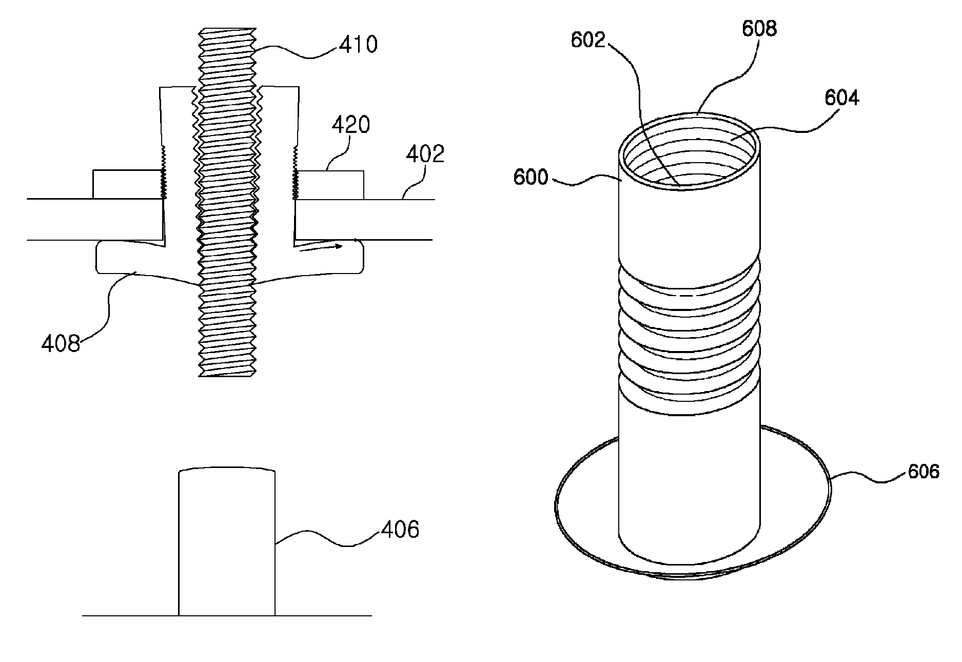
[0045]FIG. 4 is a drawing illustrating an exploded perspective view of an RF cavity filter using a tuning bolt ground connection structure according to an embodiment of the present invention, and FIG. 5 is a drawing illustrating a cross-sectional view of a cavity in an RF cavity filter using a tuning bolt ground connection structure according to an embodiment of the present invention.

[0046]Referring to FIGS. 4 and 5, an RF cavity filter using a tuning bolt ground connection structure according to an embodiment of the present invention may include a housing 400, a cover 402, multiple cavities 404, multiple resonators 406 each of which is to be included in each of the cavities, grounding bolts 408, tuning bolts 410, an input connector 412, an output connector 414, and ...


PUM


Abstract

An RF cavity filter is disclosed. The disclosed filter includes: a housing having at least one cavity defined; a cover coupled to an upper portion of the housing; at least one resonator contained within the at least one cavity; at least one hole formed in the cover; at least one grounding bolt configured to be inserted into the hole, having a screw thread formed on a part of an outer perimeter, and having a center hole in a center portion; and at least one tuning bolt inserted into the housing through the center hole along a screw thread formed on an inner perimeter of the center hole, where the grounding bolt has a flange part formed on a lower portion that is in contact with the tuning bolt and a lower portion of the cover.

Description

CROSS-REFERENCE TO RELATED APPLICATION[0001]This application is a continuation of PCT / KR2010 / 001672 filed Mar. 18, 2010, which claims the benefit of Korean Application No. 10-2009-0023256 filed Mar. 18, 2009, the entire contents of which applications are incorporated herein by reference.TECHNICAL FIELD[0002]The present invention relates to an RF cavity filter, more particularly to a tuning bolt ground connection structure included in an RF cavity filter.BACKGROUND ART[0003]A filter is an apparatus for passing only signals of specific frequency band out of all input frequency signals, and is implemented in a variety of forms. The band passing frequency of an RF filter is determined by the inductance components and capacitance components of the filter, and the work of adjusting filter characteristics such as band passing frequency and bandwidth of the filter is called tuning.[0004]FIG. 1 is a drawing illustrating the structure of a general RF cavity filter of the related art.[0005]Ref...

Claims


Application Information

Patent Timeline
Patent Type & Authority Patents(United States)
IPC IPC(8): H01P1/208H01P7/06
CPCH01P1/2084H01P1/20H01P1/203
Inventor LEE, SEUNG-CHEOL
Owner ACE TECH
Why Eureka
Try Eureka