Pilot multiplexing method and OFDM transceiver apparatus in OFDM system
a transceiver and multiplexing technology, applied in multiplex communication, orthogonal multiplex, baseband system details, etc., can solve the problems performance and cost, and the influence of data demodulation performance, so as to remove inter-symbol interference and improve reception sensitivity.
- Summary
- Abstract
- Description
- Claims
- Application Information
AI Technical Summary
Benefits of technology
Problems solved by technology
Method used
Image
Examples
first embodiment
[0054](A) First Embodiment
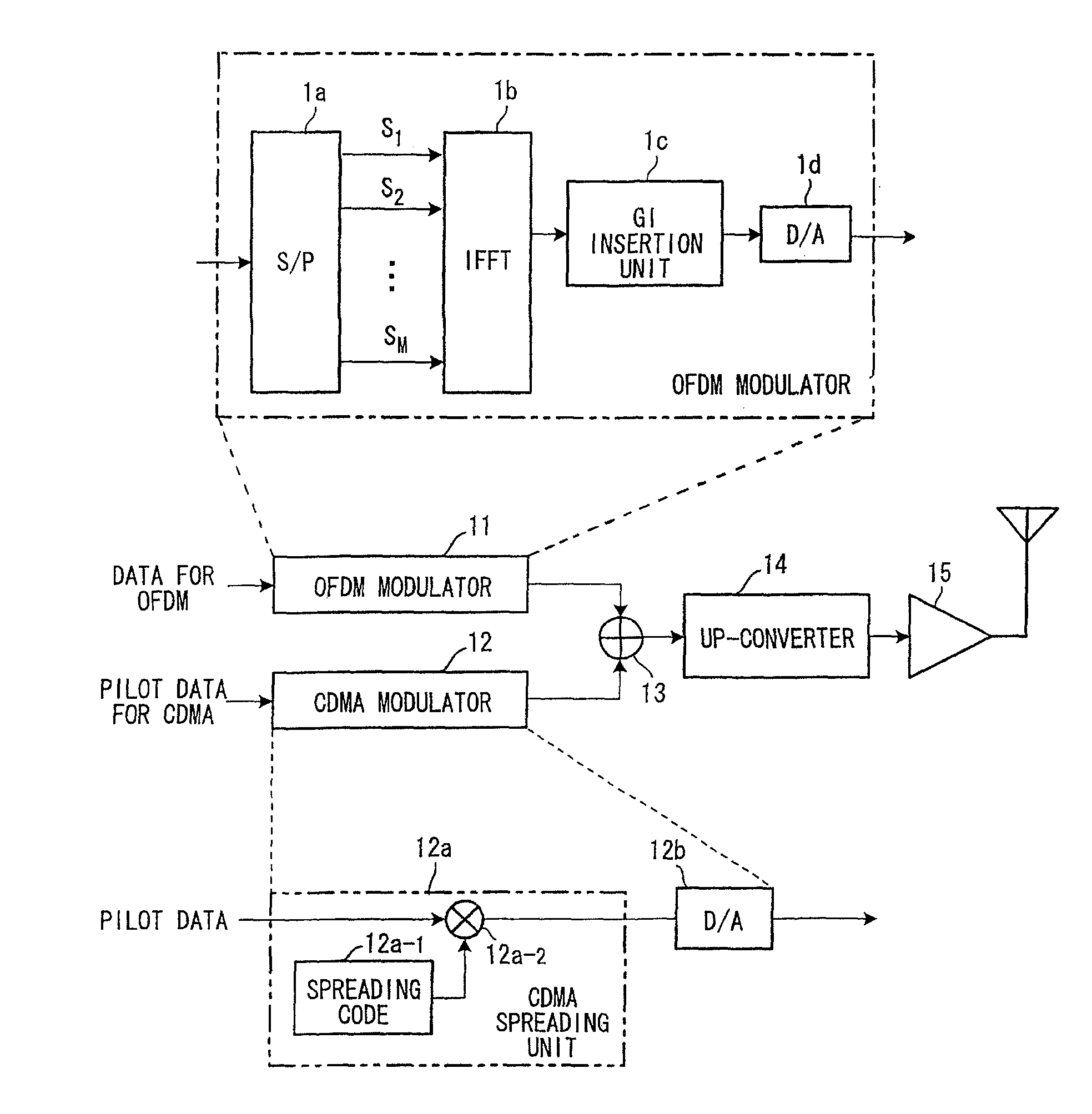
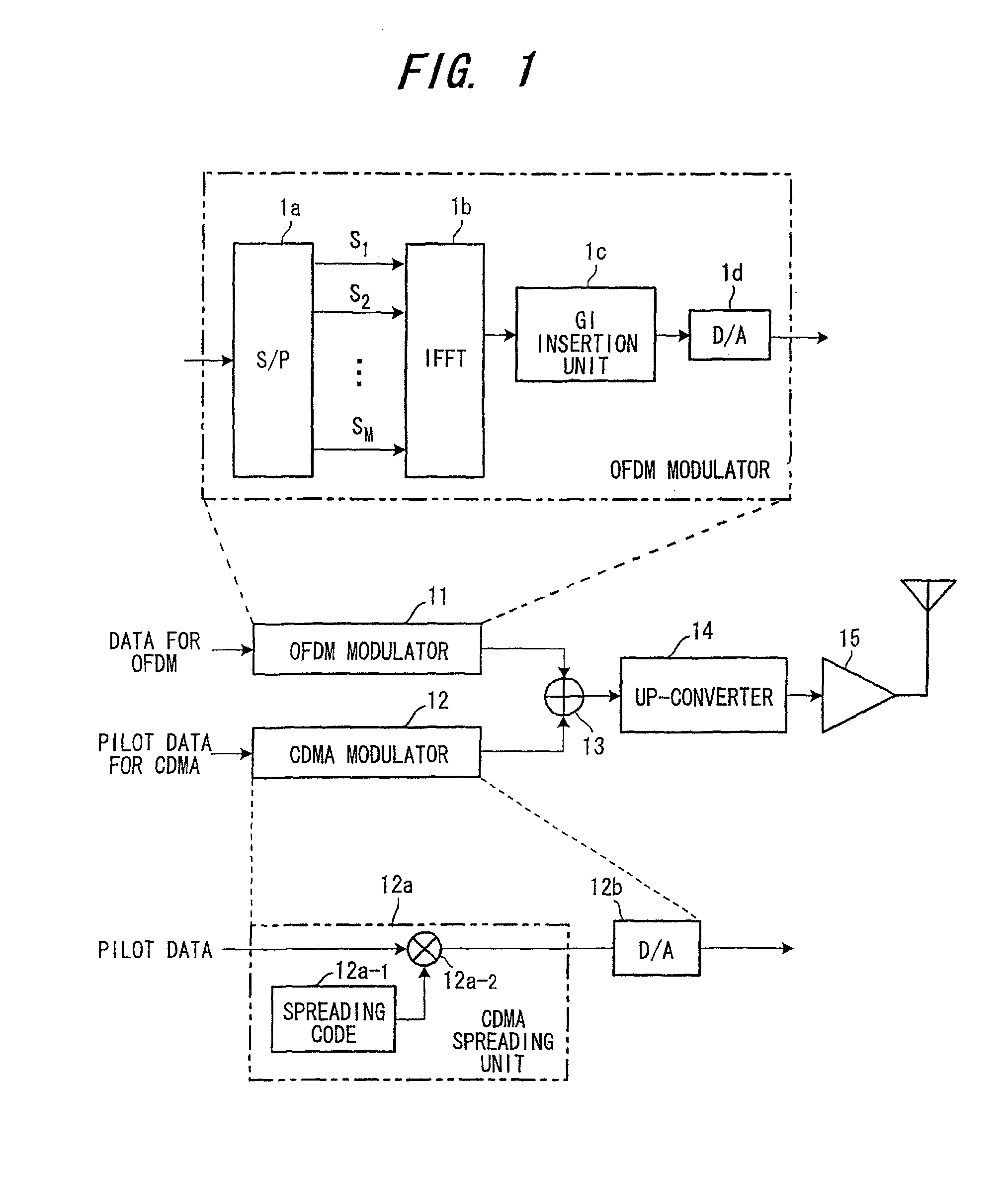
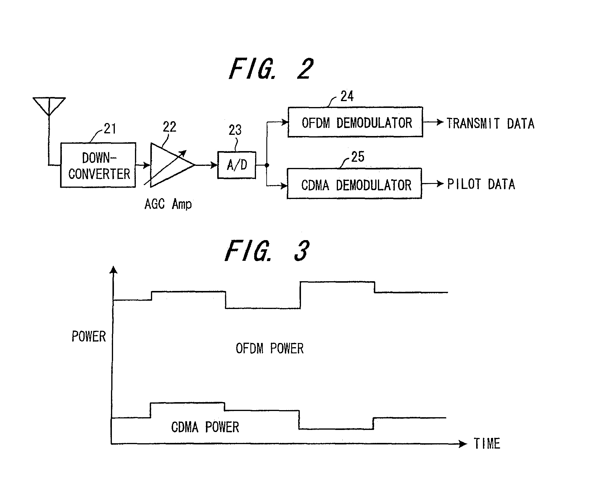
[0055]FIG. 1 is a diagram illustrating the structure of a transmitting apparatus in an OFDM system according to a first embodiment, FIG. 2 is a diagram illustrating the structure of a receiving apparatus in the OFDM system, and FIG. 3 illustrates an example of frame structure.
[0056]In the transmitting apparatus of FIG. 1, an OFDM modulator 11 has a structure identical with that of the OFDM modulator 1 in FIG. 17. The modulator applies OFDM modulation to transmit data, which enters at a prescribed bit rate, and outputs the result. A CDMA modulator 12, which has a CDMA spreading unit 12a and a DA converter 12b, spreads pilot data, which enters at a bit rate identical with that of the transmit data, by a spreading code for the pilot and outputs the result. In the CDMA spreading unit 12a, a spreading code generator 12a-1 generates the spreading code for the pilot, a multiplier 12a-2 multiplies pilot data by the spreading code to thereby directly spread the data...
second embodiment
[0059](B) Second Embodiment
[0060]FIG. 4 is a diagram illustrating the structure of a transmitting apparatus in an OFDM system according to a second embodiment, FIG. 5 is a diagram illustrating the structure of a receiving apparatus in the OFDM system, and FIG. 6 illustrates an example of frame structure.
[0061]The transmitting apparatus of FIG. 4 differs from that of FIG. 1 in the following points:
[0062]① the combiner 13 is changed to a multiplexer 31;
[0063]② items of transmit data DT and pilot data P are input to the OFDM modulator 11 and CDMA modulator 12, respectively, at the timing shown in FIG. 6; and
[0064]③ a multiplexer 31 selects and outputs CDMA signals and OFDM signals in time-division fashion at the timing shown in FIG. 6.
[0065]More specifically, in the transmitting apparatus of FIG. 4, the separately provided OFDM modulator 11 and CDMA modulator 12 input an OFDM signal and CDMA signal of the same frequency band, these signals being obtained by OFDM and CDMA modulation app...
third embodiment
[0071](C) Third Embodiment
[0072]In FIG. 7, (A) is a diagram showing the structure of a timing detection unit for detecting OFDM frame timing and OFDM symbol timing in a receiving apparatus.
[0073]The transmitting apparatus transmits the OFDM signal and CDMA signal by the arrangement of either the first or second embodiment, The CDMA signal is generated and transmitted by spreading known pilot data at a specific timing (e.g., the frame timing) by a known spreading code for timing.
[0074]A matched filter 41 in the timing detection unit of the receiving apparatus performs a correlation operation by multiplying the A / D-converted receive signal by the transmit-side known spreading code for timing. An averaging unit 42 calculates an average Xj of correlation at each time tj using a plurality of results of the correlation operation. A power calculation unit 43 calculates the power of the correlation value Xj at each time and generates a delay profile shown in FIG. 8. From the delay profile, ...
PUM
 Abstract
Description
Claims
Application Information
 - R&D
- Intellectual Property
- Life Sciences
- Materials
- Tech Scout
- Unparalleled Data Quality
- Higher Quality Content
- 60% Fewer Hallucinations
Browse by: Latest US Patents, China's latest patents, Technical Efficacy Thesaurus, Application Domain, Technology Topic, Popular Technical Reports.
© 2025 PatSnap. All rights reserved.Legal|Privacy policy|Modern Slavery Act Transparency Statement|Sitemap|About US| Contact US: help@patsnap.com


