Encoding apparatus, method of controlling thereof, and computer program
a technology of encoding apparatus and control method, applied in the direction of signal generator with optical-mechanical scanning, color television with bandwidth reduction, etc., can solve the problems of image quality varies and the inability to perform adaptive quantization for images, and achieve the effect of suppressing image quality degradation
- Summary
- Abstract
- Description
- Claims
- Application Information
AI Technical Summary
Benefits of technology
Problems solved by technology
Method used
Image
Examples
first embodiment
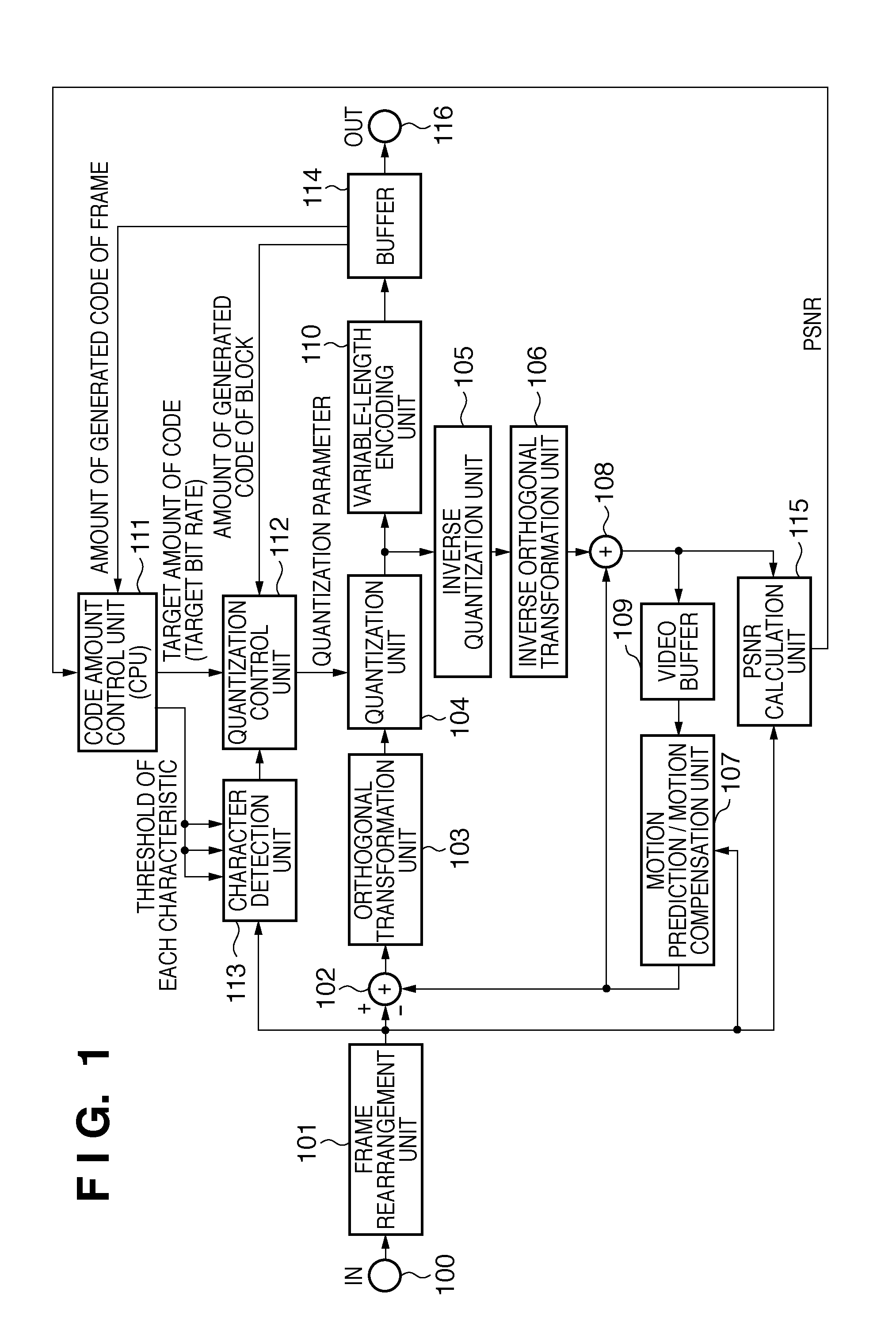
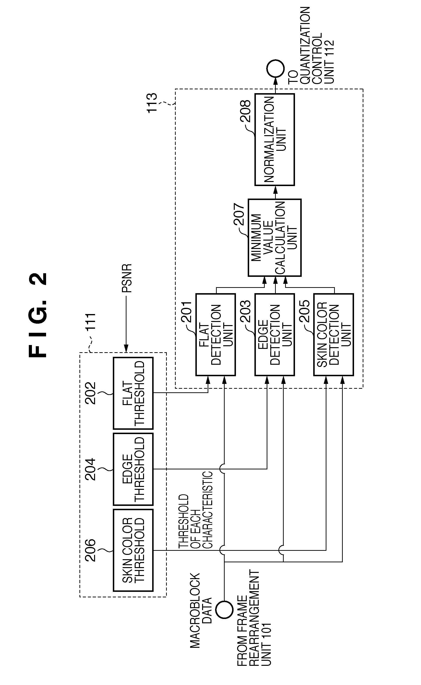
[0037]The first embodiment will be described with reference to FIGS. 1 to 3C. FIG. 1 is a block diagram showing an example of the overall arrangement of an encoding apparatus according to this embodiment. FIGS. 2, and 3A to 3C are views for explaining character detection according to this embodiment. FIG. 4 is a graph for explaining PSNR. FIGS. 5A to 5C are graphs showing the relationships between PSNR and thresholds.
[0038]FIG. 1 shows an encoding apparatus according to the embodiment of the present invention. This apparatus can be implemented as a video and audio signal recording apparatus such as a digital video camera. The apparatus supports an encoding method such as MPEG (Moving Pictures of Experts Group) or H.264 / AVC (Advanced Video Coding).
[0039]Referring to FIG. 1, an input signal 100, which is generated by dividing moving images into predetermined blocks, is input to the encoding apparatus. In, e.g., MPEG, 16×16 or 8×8 blocks are used. The size is determined by the encoding...
second embodiment
[0066](Second Embodiment)
[0067]In the first embodiment, the character detection unit 113 determines whether visual degradation in each macroblock is noticeable by using PSNR representing the degree of degradation of an image. In the second embodiment, the threshold to be provided to each detection unit is controlled depending on whether a flicker is likely to occur in an image that is played back.
[0068]FIG. 6 is a block diagram showing an example of the overall arrangement of an encoding apparatus according to the second embodiment. The basic arrangement is the same as in the first embodiment except that a mechanism for detecting a flicker is added to the arrangement in FIG. 1. The arrangement of a character detection unit 613 is the same as that of the character detection unit 113 in FIG. 1 and will therefore be described with reference to FIG. 2.
[0069]Referring to FIG. 6, the encoding apparatus includes a frame rearrangement unit 601, addition / subtraction unit 602, an orthogonal t...
third embodiment
[0088](Third Embodiment)
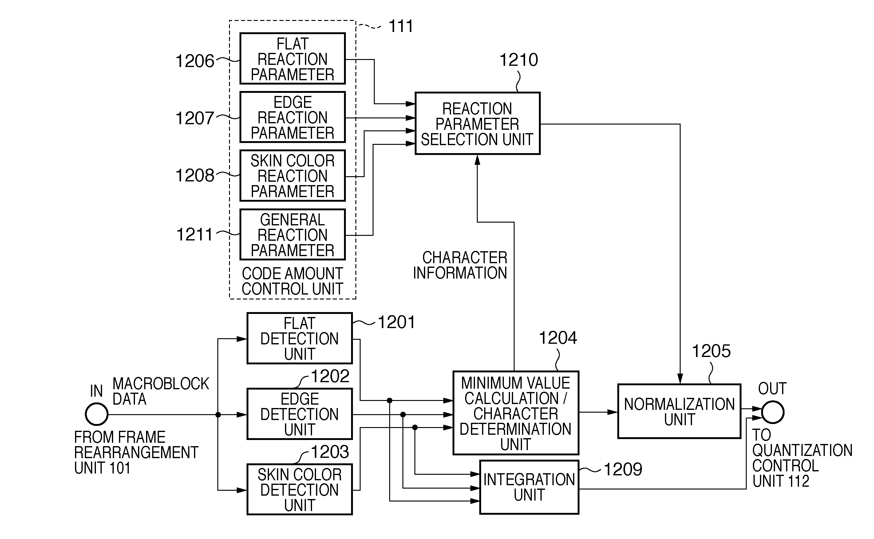
[0089]The arrangement of an encoding apparatus according to this embodiment is the same as in FIG. 1. In this embodiment, however, the encoding apparatus need not include a PSNR calculation unit 115. FIG. 9 is a block diagram showing the schematic arrangement of a character detection unit 113. FIGS. 10A and 10B and FIGS. 11A to 11C are views for explaining the operation.
[0090]FIG. 9 is a block diagram showing the schematic arrangements of a code amount control unit 111 and the character detection unit 113 according to this embodiment. A flat detection unit 1201 detects the degree (level) of a flat block from the image data of each macroblock from a frame rearrangement unit 101. An edge detection unit 1202 detects the degree (level) of an edge from the image data from the frame rearrangement unit 101. A skin color detection unit 1203 detects the degree (level) of a skin color from the image data from the frame rearrangement unit 101. The detection characterist...
PUM
 Abstract
Description
Claims
Application Information
 - R&D
- Intellectual Property
- Life Sciences
- Materials
- Tech Scout
- Unparalleled Data Quality
- Higher Quality Content
- 60% Fewer Hallucinations
Browse by: Latest US Patents, China's latest patents, Technical Efficacy Thesaurus, Application Domain, Technology Topic, Popular Technical Reports.
© 2025 PatSnap. All rights reserved.Legal|Privacy policy|Modern Slavery Act Transparency Statement|Sitemap|About US| Contact US: help@patsnap.com


