Molded synthetic hip, ridge or rake shingle and process and apparatus for molding same

a synthetic hip and ridge shingle technology, applied in the field of shingle manufacture, can solve the problems of increasing the weight applied to the roof, increasing the cost of the roof, and increasing the use of natural materials, so as to shorten the molding time

Active Publication Date: 2013-02-12
CERTAINTEED CORP
View PDF14 Cites 21 Cited by
  • Summary
  • Abstract
  • Description
  • Claims
  • Application Information

AI Technical Summary

Benefits of technology

[0008]The rack has a shape such that the radius of the bend varies from the upper or headlap portion of the shingle precursor to the lower exposure or finished look or tab portion of the shingle. The internal radius or the internal angle is tighter in the upper end of the headlap portion than at the lower end of the tab portion of the shingle precursor. Generally, the internal angle or radius of the finished end of the shingle is such that it matches the exterior radius of the shingle thus formed, about halfway along the length of the shingle precursor. Because of the variable radius of the bend along the length of the shingle precursor, an overlying shingle, thus formed, in an array of such shingles when installed on a roof, fits snuggly nested over an underlying shingle on a hip, ridge or rake. This also helps in alignment and placement of shingles along a hip, ridge or rake during installation because they fit together well in the optimal configuration on the roof.
[0010]Because the shingle material is still somewhat soft when it is being molded in the compression mold, by using a carrier plate to carry such material while it is in the compression mold, the duration of the shingle material in the compression mold may be shortened. Additionally, by having a surface configuration to the carrier plate that is the reciprocal of the surface configuration of the shingle, it is not necessary that the mold itself have a supporting surface beneath the shingle that is being molded, that is a reciprocal surface configuration for the adjacent surface of the roofing shingle. Thus, the carrier plate becomes the bottom of the mold during compression molding. The carrier plate also allows for automation and handling of the part.

Problems solved by technology

Generally, the use of natural materials has become very expensive.
Additionally, the use of natural materials in many instances, such as slate shingles or tiles, can greatly increase the weight applied to a roof, often requiring additional support for the roof, which again can increase the expense of a roof.

Method used


Image

  • Molded synthetic hip, ridge or rake shingle and process and apparatus for molding same
  • Molded synthetic hip, ridge or rake shingle and process and apparatus for molding same
  • Molded synthetic hip, ridge or rake shingle and process and apparatus for molding same

Examples


Embodiment Construction

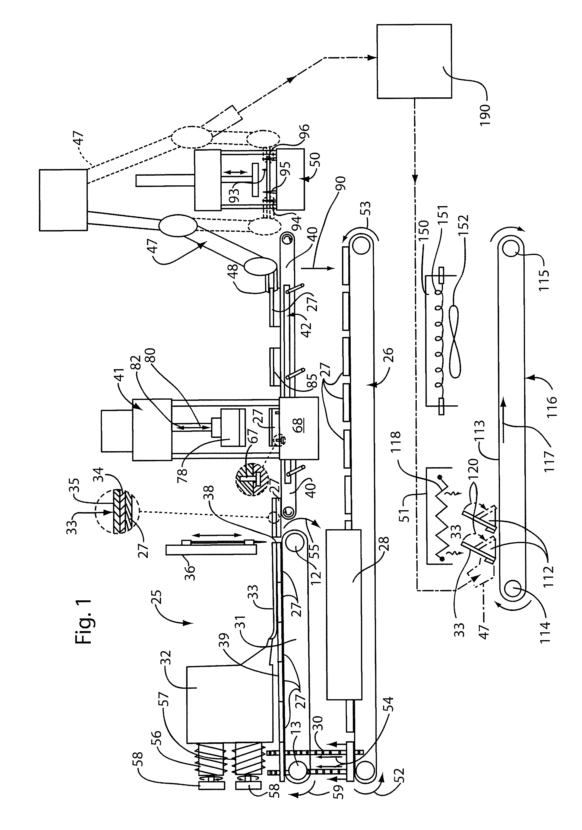
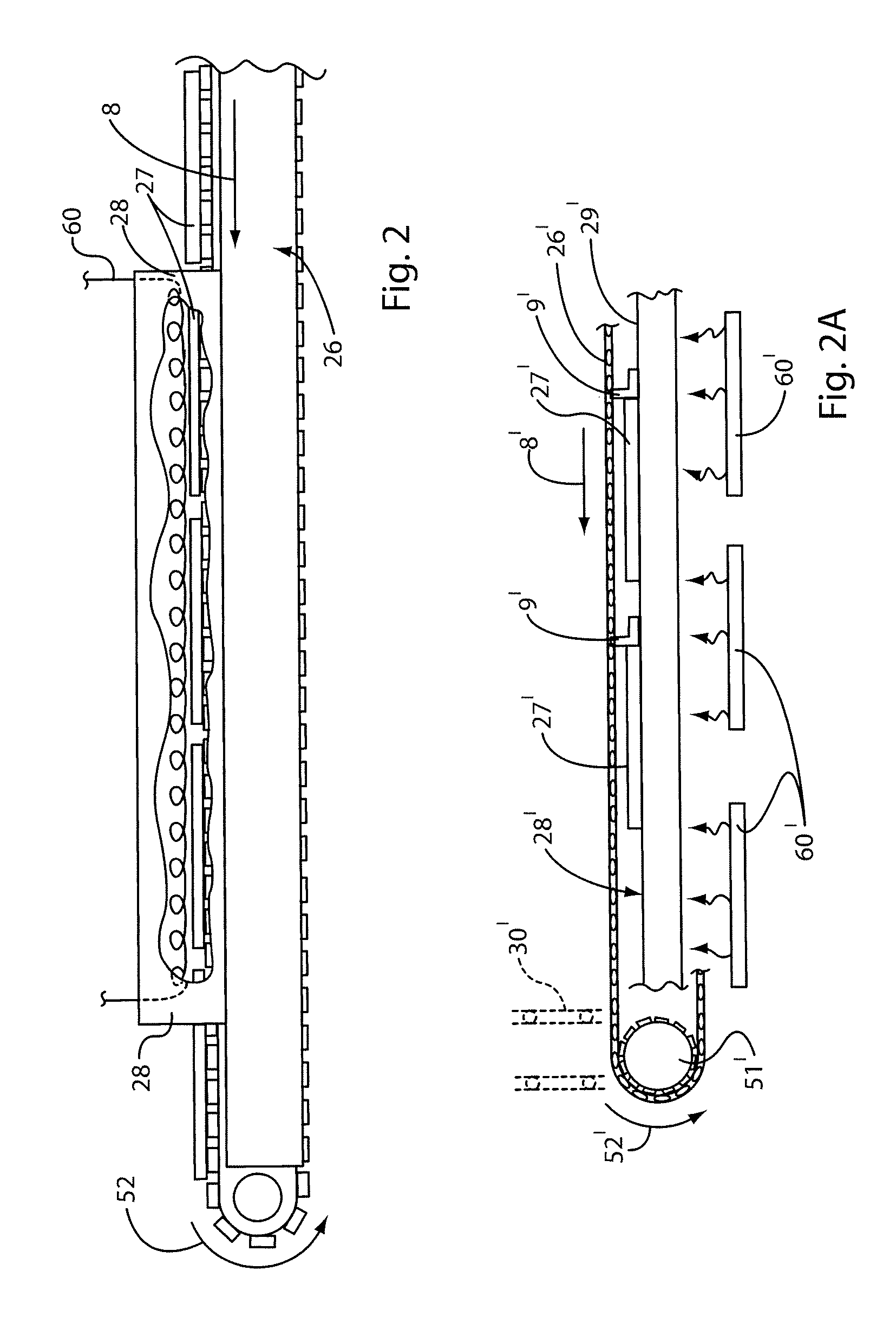
[0039]Referring now to the drawings in detail, reference is first made to FIG. 1, wherein the apparatus of this invention is generally designated by the numeral 25 as comprising a preliminary conveyor apparatus 26 for delivering carrier plates 27 through a carrier plate preheater apparatus 28, as shown in perspective view in FIG. 3, whereby the carrier plates are delivered via a transfer mechanism 30 to an extruder conveyor apparatus 31 between rotatable end shafts 12, 13, whereby the carrier plates are delivered beneath an extruder apparatus 32, shown in larger view in FIG. 5, of the type preferably having a pair of single screw extruders 56, 57, by which a co-extruded sheet of shingle material 33, preferably comprised of a core material 34 covered by a layer of capstock material 35 is co-extruded onto the carrier plates 27, as is shown more clearly in perspective view in FIG. 4, and the carrier plates are delivered end-to-end therebeneath, as shown in FIG. 1.

[0040]The carrier plat...


PUM


Abstract

A molded hip, ridge or rake shingle is provided that is shaped to fit over angled intersecting planar surface of a roof hip, ridge or rake, by making a shingle precursor and draping it in heated condition over a rack having surfaces that have an included angle therebetween to cool and take form, such that portions of the shingle precursor conform to the surfaces of the rack, at a desired predetermined included angle between the shingle precursor portions, to form a hip, ridge or rake shingle with shingle portions having the desired included angle between the shingle portions. The shingle is formed according to the process, and on an apparatus, to produce the shingles that can be applied to a roof, in an array of shingles.

Description

CROSS-REFERENCE TO RELATED APPLICATIONS[0001]This application is based upon U.S. provisional application 61 / 099,330, filed Sep. 23, 2008, from which this application claims priority.BACKGROUND OF THE INVENTION[0002]In the art of shingle manufacture, it is known to produce shingles of natural materials, such as slate, cedar shakes, and tiles, all for use on roofs, to give a rich, highly aesthetic appearance to the roofs of homes or other buildings.[0003]Generally, the use of natural materials has become very expensive. Additionally, the use of natural materials in many instances, such as slate shingles or tiles, can greatly increase the weight applied to a roof, often requiring additional support for the roof, which again can increase the expense of a roof.[0004]Accordingly, there has developed the use of synthetic materials which can be molded or otherwise formed, to give the appearance of natural materials, but which can be lighter in weight than the natural materials they are desi...

Claims


Application Information

Patent Timeline
Patent Type & Authority Patents(United States)
IPC IPC(8): E04B7/02E04B7/00
CPCE04D1/30E04D2001/305
Inventor SHANES, LARRY WAYNEMACKINNON, THOMAS KEVIN
Owner CERTAINTEED CORP
Why Eureka
Try Eureka