
Thermal printer

a printer and thermal technology, applied in the field of thermal printers, can solve the problems of difficult correction of problems and difficult fixation of paper jams, and achieve the effect of simple recovery and recovery

Active Publication Date: 2013-02-12
SEIKO EPSON CORP
View PDF9 Cites 3 Cited by
  • Summary
  • Abstract
  • Description
  • Claims
  • Application Information

AI Technical Summary

Benefits of technology

The invention prevents recording paper from getting caught in gaps between different parts of a thermal printer. This is done by overlapping parts of the head mounting member and front guide member, which prevents gaps in the paper path. Additionally, a detector is used to detect if recording paper has entered the gap and can alert the user to stop the thermal printer, preventing the paper from getting jammed and difficult to recover. Overall, this invention ensures smoother printing and easier recovery of paper.

Problems solved by technology

As a result, the recording paper could enter either of these gaps after passing the printing position and cause a jam at a position outside the paper transportation path where fixing the paper jam is difficult.
When the recording paper enters the gap between the platen roller and the back guide member in this aspect of the invention, rotation of the platen roller can be stopped before the recording paper jams at a position removed from the paper transportation path and causes a problem that is difficult to correct.

Method used


Image

  • Thermal printer
  • Thermal printer
  • Thermal printer

Examples


Embodiment Construction

[0028]A preferred embodiment of a thermal printer according to the invention is described below with reference to the accompanying figures.

* General Configuration

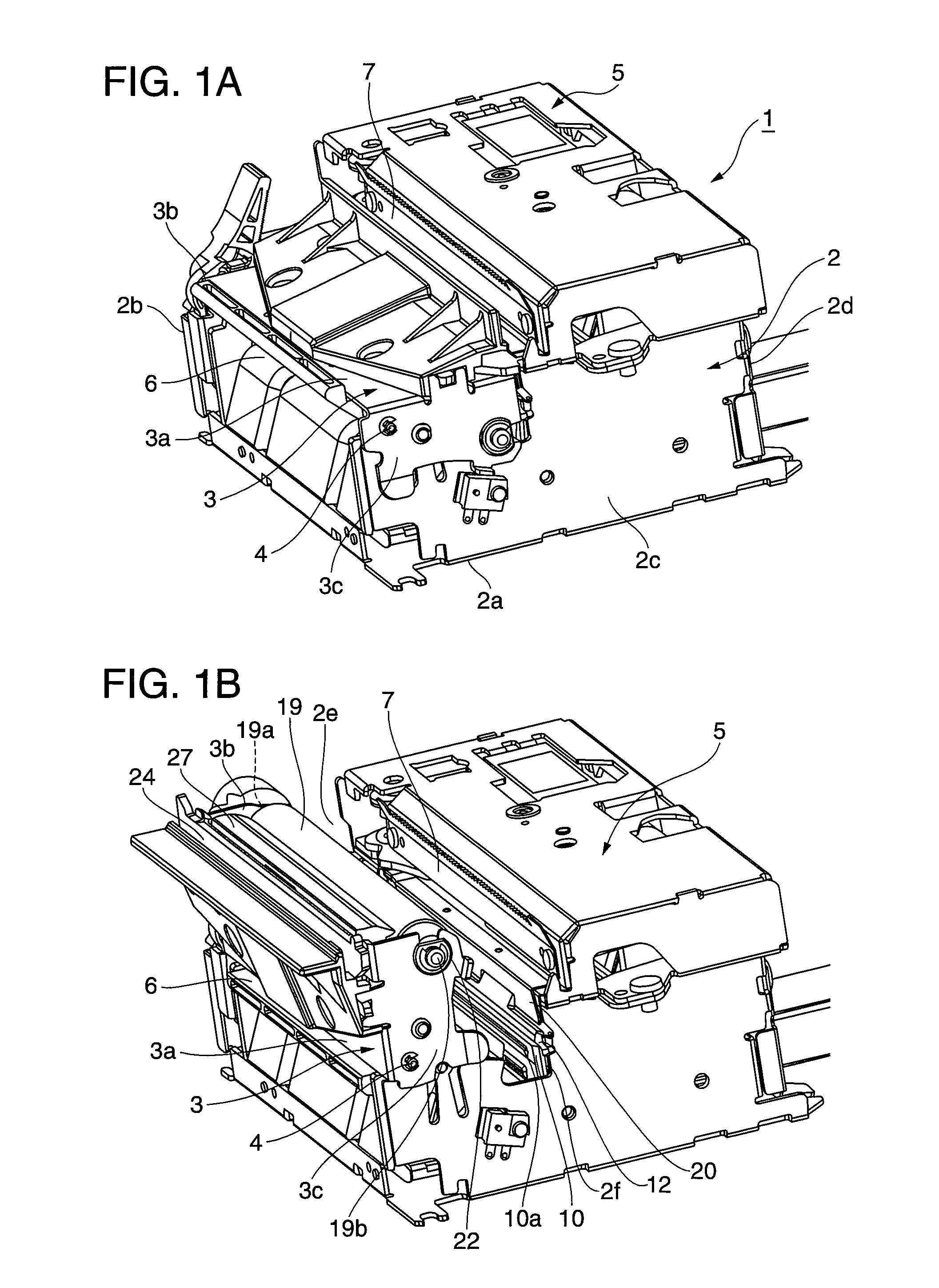
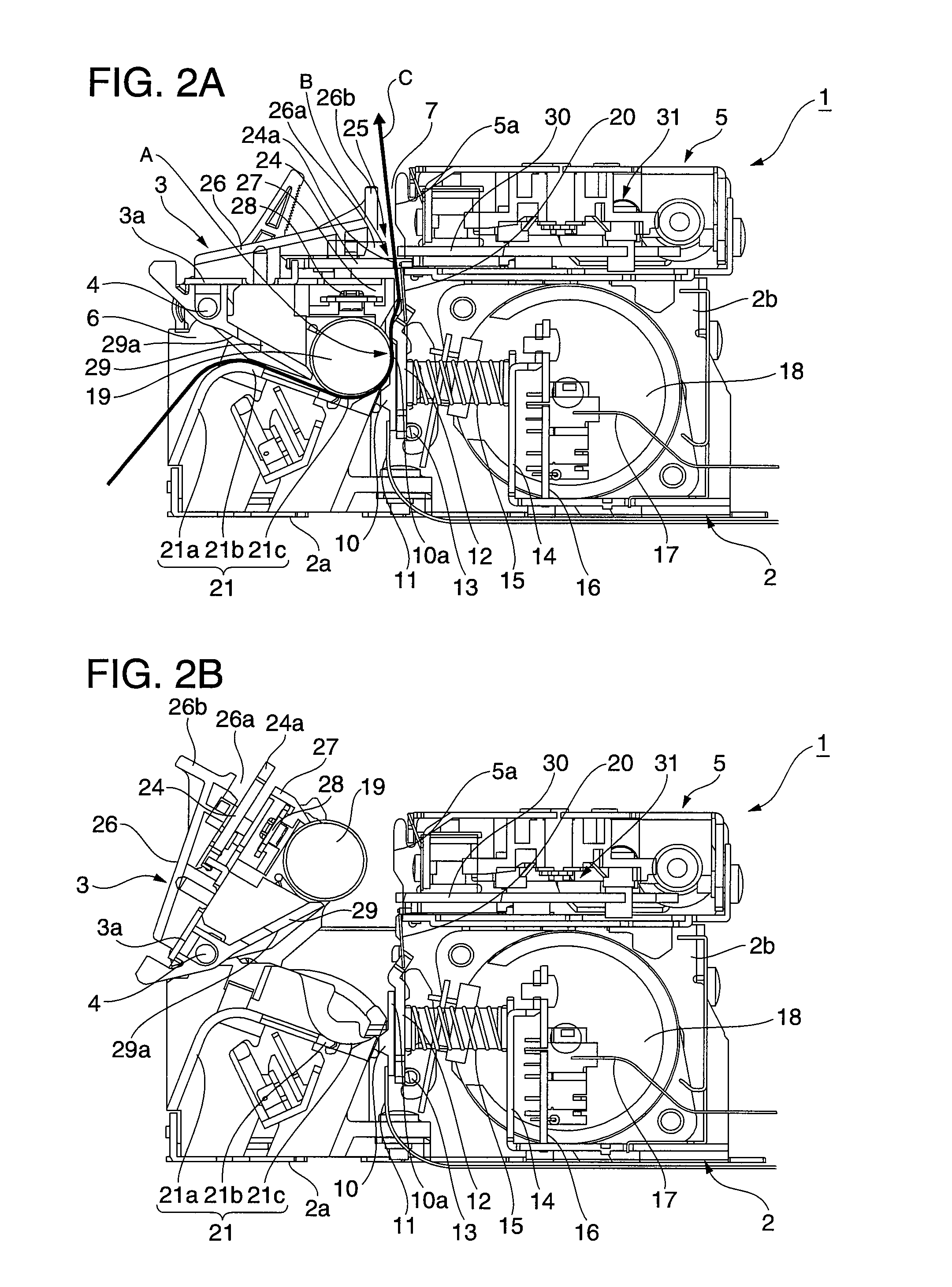
[0029]FIG. 1A and FIG. 1B are oblique views of the printing mechanism of a thermal printer according to this embodiment of the invention. FIG. 1A shows the pivot frame in the closed position, and FIG. 1B shows the pivot frame in the open position. FIG. 2A and FIG. 2B are vertical section views of the printing mechanism shown in FIG. 1, FIG. 2A showing the pivot frame closed and FIG. 2B showing the pivot frame open.

[0030]As shown in FIG. 1, the printing mechanism 1 has a rectangular printer frame 2 made of sheet metal. The printer frame 2 includes a bottom panel 2a, left and right side panels 2b and 2c, and a back panel 2d. A sheet metal pivot frame 3 extends widthwise to the paper frame at the top front part of the printer frame 2.

[0031]The pivot frame 3 is supported pivotably on a horizontal shaft 4 that extends widthwise ...


PUM


Abstract

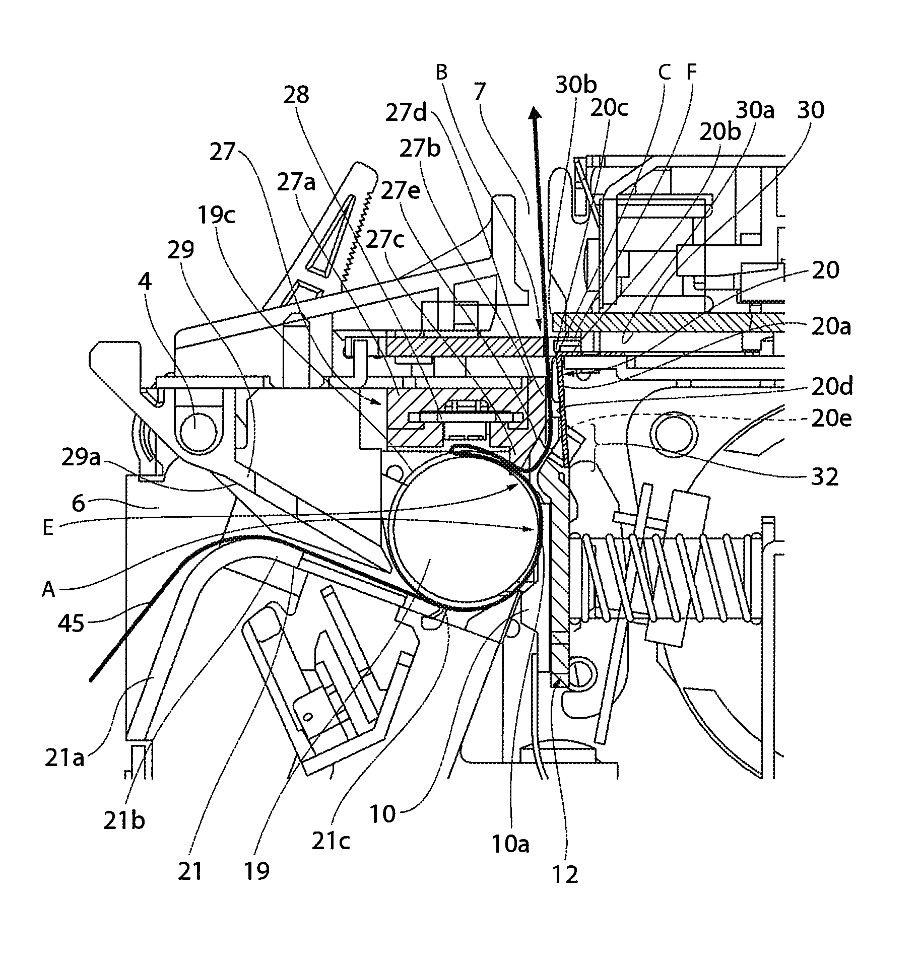
A thermal printer avoids or reduces difficult to correct problems caused by recording paper that has passed the printing position leaving the paper transportation path. A printing mechanism has a head mounting plate that carries a line thermal head, a front guide plate disposed downstream from the head mounting plate, a platen roller that defines the printing position A, and a back guide member disposed downstream from the platen roller. The head mounting plate and front guide plate have interlocking parts that interlock with each other widthwise to the paper transportation path. A paper detector that detects entry of the recording paper 45 is disposed to a gap E between the back guide member and platen roller. When the paper detector detects the recording paper 45, a rotation control unit stops the platen roller.

Description

BACKGROUND[0001]1. Technical Field[0002]The present invention relates to a thermal printer that can avoid or reduce paper jams and other problems that are difficult to correct as a result of recording paper leaving the paper transportation path after passing the printing position.[0003]2. Related Art[0004]Recording paper is printed in a thermal printer by pressing the recording paper against a thermal head by means of a platen roller at a printing position located along the paper transportation path. In the thermal printer described in Japanese Unexamined Patent Appl. Pub. JP-A-2008-30301, the thermal head is carried on a head mounting plate that can move to and away from the platen roller, and contact pressure is held between the thermal head and platen roller as a result of the head mounting plate being urged to the platen roller side by a compression coil spring.[0005]After the recording paper passes the printing position in this type of thermal printer, the front surface that wa...

Claims


Application Information

Patent Timeline
Patent Type & Authority Patents(United States)
IPC IPC(8): B41J11/00
CPCB41J2/32B41J13/14B41J11/006
Inventor YAMADA, RIKUO
Owner SEIKO EPSON CORP
Learn More