Implantable valve prosthesis for treating venous valve insufficiency

a technology of venous valve and prosthesis, which is applied in the field of valve prosthesis, can solve the problems of varicose vein formation, distended veins typically located in the leg, and retrograde blood flow in the veins

Active Publication Date: 2013-02-19
MEDTRONIC VASCULAR INC
View PDF15 Cites 105 Cited by
  • Summary
  • Abstract
  • Description
  • Claims
  • Application Information

AI Technical Summary

Benefits of technology

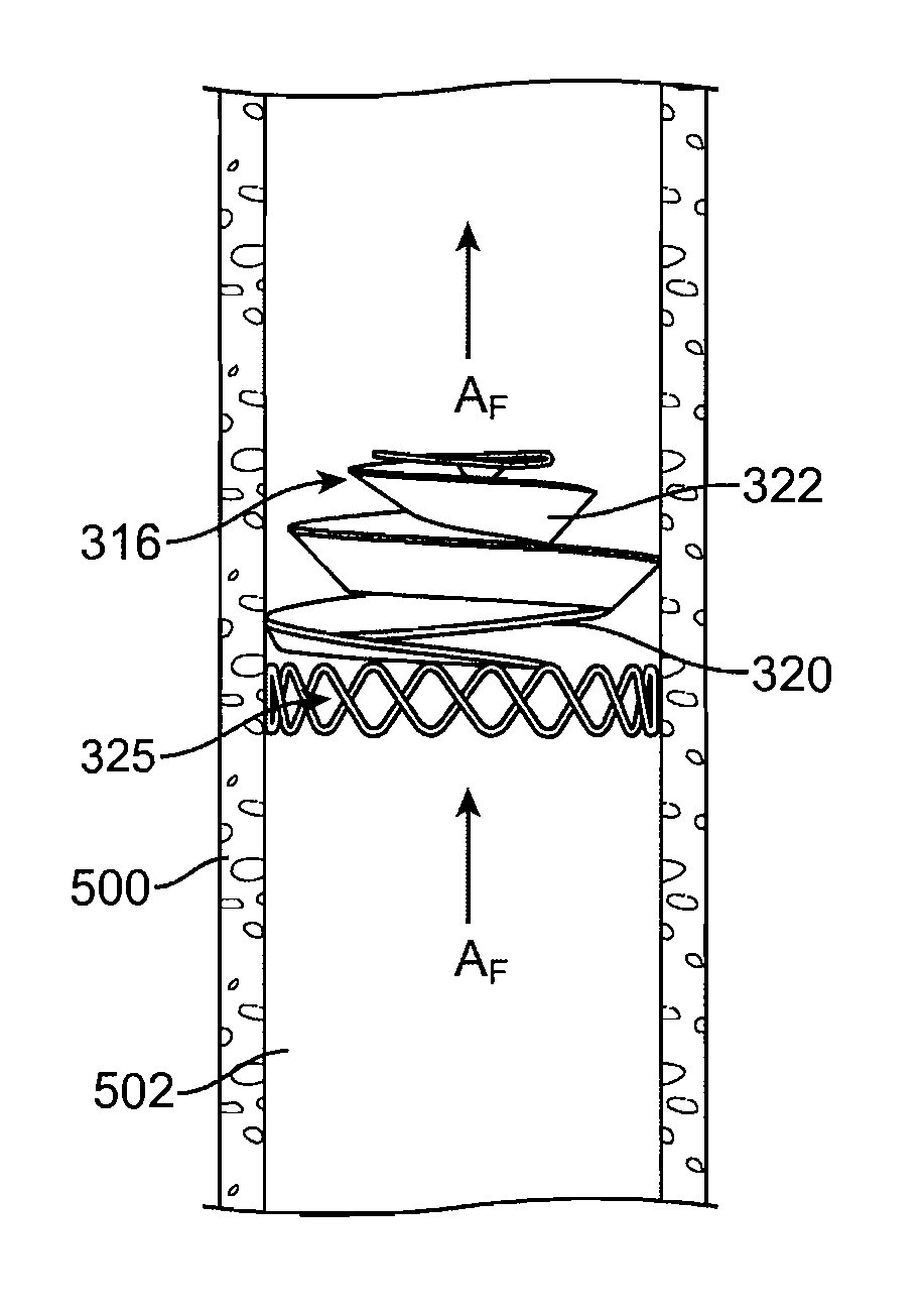
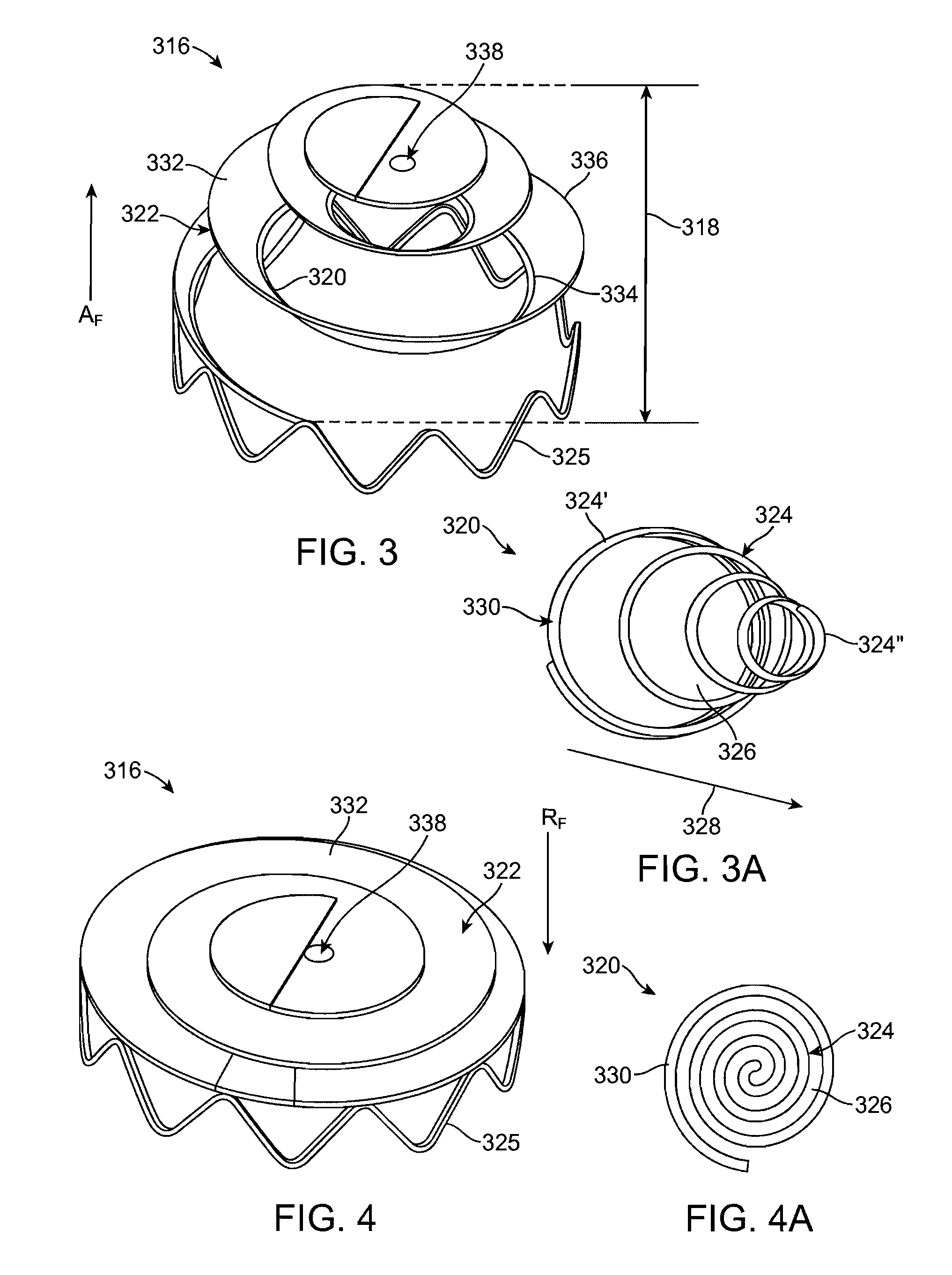
[0010]Embodiments hereof are directed to an one-way venous valve prosthesis for percutaneous placement within a vein. The prosthesis has a body portion including a valve scaffold and a backflow barrier. The body portion is operable to alternate between an open configuration wherein the valve scaffold has a frustoconical coil shape of consecutive windings with open spaces therebetween, and a closed configuration wherein the consecutive windings of the valve scaffold are collapsed such that the valve scaffold has a flat profile. The backflow barrier allows blood flow through the open spaces between consecutive windings of the valve scaffold when the body portion is in the open configuration and the backflow barrier covers the open spaces between consecutive windings of the valve scaffold to prevent blood flow through the valve prosthesis when the body portion is in the closed configuration.

Problems solved by technology

Incompetent valves can also lead to reflux of blood from the deep venous system to the superficial venous system and the formation of varicose veins.
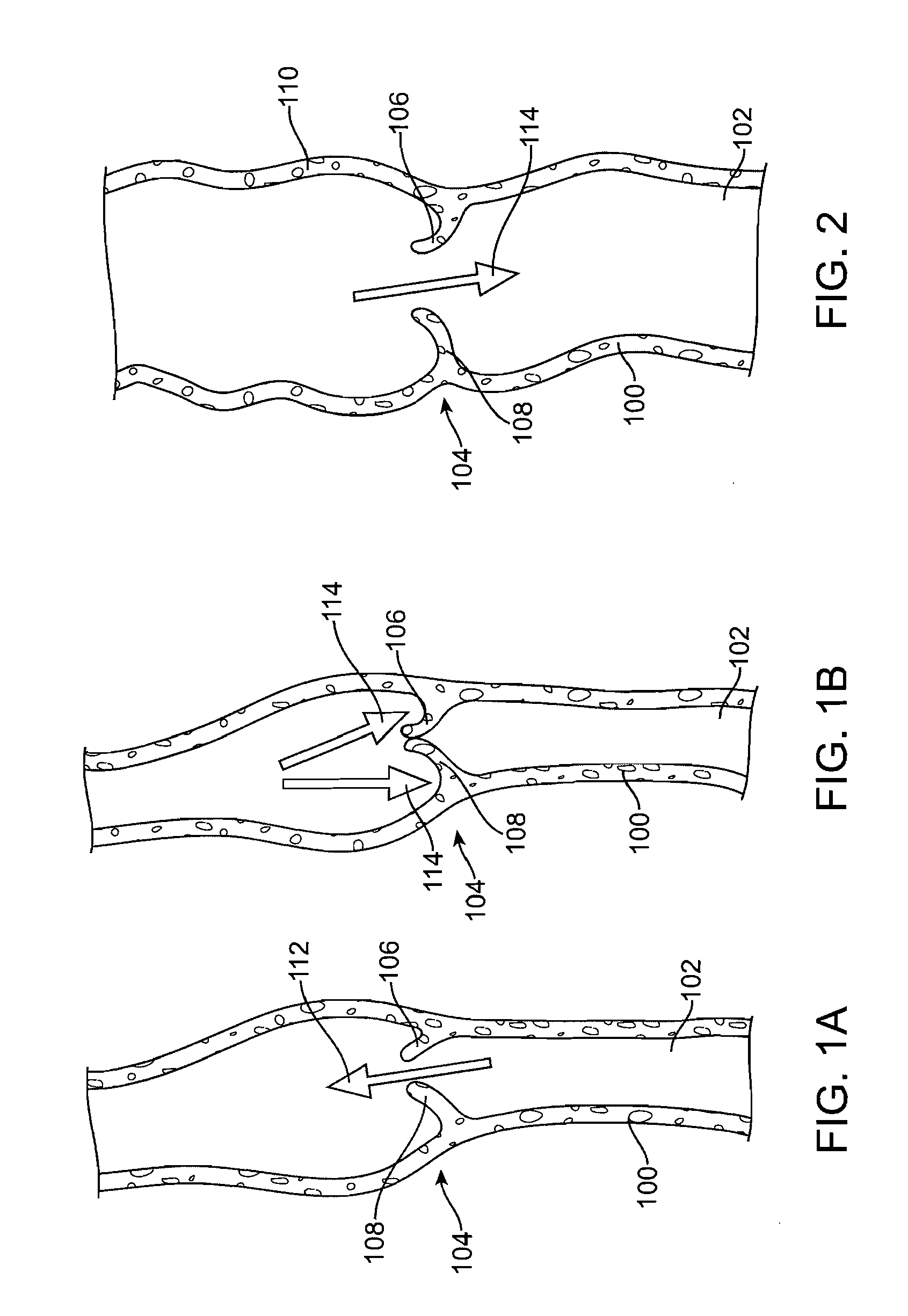
Veins typically located in the leg can become distended from prolonged exposure to excessive pressure and due to weaknesses found in the vessel wall causing the natural venous valves to become incompetent leading to retrograde blood flow in the veins.
Such veins no longer function to help pump or direct the blood back to the heart during normal walking or use of the leg muscles.
As a result, blood tends to pool in the lower leg and can lead to leg swelling and the formation of deep venous thrombosis and phlebitis.
The formation of thrombus in the veins can further impair venous valvular function by causing valvular adherence to the venous wall with possible irreversible loss of venous function.
Continued exposure of the venous system to blood pooling and swelling of the surrounding tissue can lead to post phlebitic syndrome with a propensity for open sores, infection, and may lead to limb amputation.
Such patients are at increased risk for development of soft tissue necrosis, ulcerations, pulmonary embolism, stroke, heart attack, and amputations.
After a vein segment becomes incompetent, the vessel wall dilates and fluid velocity there through decreases, which may lead to flow stasis and thrombus formation in the proximity of the venous valve.
Repair and replacement of venous valves presents a formidable challenge due to the low blood flow rate found in native veins, the very thin wall structure of the venous wall and the venous valve, and the ease and frequency of which venous blood flow can be impeded or totally blocked for a period of time.
However, such prostheses have not been devoid of problems, such as thrombus formation and valve failure due to leaflet thickening / stiffening, non-physiologic flow conditions, non-biocompatible materials and / or excessive dilation of the vessels with a subsequent decrease in blood flow rates.
In addition, many venous valve prostheses include leaflets and / or hinged flaps and are similar to valves placed into the heart, which are complex and designed for high blood pressures associated with the heart instead of lower venous blood pressures associated with veins in the lower extremities.

Method used


Image

  • Implantable valve prosthesis for treating venous valve insufficiency
  • Implantable valve prosthesis for treating venous valve insufficiency
  • Implantable valve prosthesis for treating venous valve insufficiency

Examples


Embodiment Construction

[0022]Specific embodiments of the present invention are now described with reference to the figures, wherein like reference numbers indicate identical or functionally similar elements. The terms “distal” and “proximal” are used in the following description with respect to a position or direction relative to the treating clinician. “Distal” or “distally” are a position distant from or in a direction away from the clinician. “Proximal” and “proximally” are a position near or in a direction toward the clinician.

[0023]The following detailed description is merely exemplary in nature and is not intended to limit the invention or the application and uses of the invention. Although the description of the invention is in the context of treatment of blood vessels such as the superficial and deep veins of a leg, the invention may also be used in any other body passageways where it is deemed useful. Furthermore, there is no intention to be bound by any expressed or implied theory presented in t...


PUM


Abstract

A valve prosthesis for percutaneous placement within a vein is disclosed that includes a valve scaffold and a backflow barrier. The valve scaffold is of a shape memory or resilient material and the backflow barrier is a flap of flexible material attached to the valve scaffold. The valve prosthesis is operable to alternate between open and closed configurations in response to changes in retrograde blood flow pressure. In the open configuration, the valve scaffold has a frustoconical coil shape of consecutive windings with open spaces therebetween and the backflow barrier allows antegrade blood flow through the open spaces. In the closed configuration, the consecutive windings of the valve scaffold are collapsed such that the valve scaffold has a substantially flat profile and the backflow barrier covers the opens spaces of the flattened valve scaffold to prevent retrograde blood flow from leaking there through.

Description

FIELD OF THE INVENTION[0001]The invention relates to valve prostheses for percutaneous placement within a vein.BACKGROUND OF THE INVENTION[0002]Venous valves are found within native venous vessels and are used to assist in returning blood back to the heart in an antegrade direction from all parts of the body. The venous system of the leg for example includes the deep venous system and the superficial venous system, both of which are provided with venous valves which are intended to direct blood toward the heart and prevent backflow or retrograde flow which can lead to blood pooling or stasis in the leg. Incompetent valves can also lead to reflux of blood from the deep venous system to the superficial venous system and the formation of varicose veins. Superficial veins which include the greater and lesser saphenous veins have perforating branches in the femoral and popliteal regions of the leg that direct blood flow toward the deep venous system and generally have a venous valve loca...

Claims


Application Information

Patent Timeline
Patent Type & Authority Patents(United States)
IPC IPC(8): A61F2/06A61F2/24
CPCA61F2/2427A61F2/2469A61F2/2475A61F2230/0091
Inventor THOMPSON, DUSTIN
Owner MEDTRONIC VASCULAR INC
Why Eureka
Try Eureka