Prosthesis

a technology for prosthesis and hip joint, applied in the field of prosthesis, can solve the problems of re-formation of the bone, endangering the function of the hip joint, and further erosion,

Active Publication Date: 2013-02-19
MATORTHO
View PDF16 Cites 8 Cited by
  • Summary
  • Abstract
  • Description
  • Claims
  • Application Information

AI Technical Summary

Problems solved by technology

Diseases such as rheumatoid- and osteo-arthritis can cause erosion of the articular cartilage so that the components of the joint rub together causing pain and further erosion.
Bone erosion may cause the bones themselves to attempt to compensate for the erosion which may result in the bone being reshaped.
This misshapen joint may cause pain and may eventually cease to function altogether.
Whilst joints of this kind go some way to addressing the requirement for an acceptable interphalangeal prosthesis, they suffer from various disadvantages including the long-term stiffening of the joint.
Whilst these arrangements go some way to resolving the problems detailed above, they still suffer from certain disadvantages and drawbacks.
In particular, they generally require substantial resection of the bone into which the prosthesis component is to be inserted before the prosthesis can be used.
This is not generally desirable.
Further, as the resection required to accommodate these devices is flat to accommodate the flat underside of the prosthesis, there is a high risk of damage to, or a loss of, the collateral ligaments.

Method used


Image

  • Prosthesis
  • Prosthesis
  • Prosthesis

Examples


Embodiment Construction

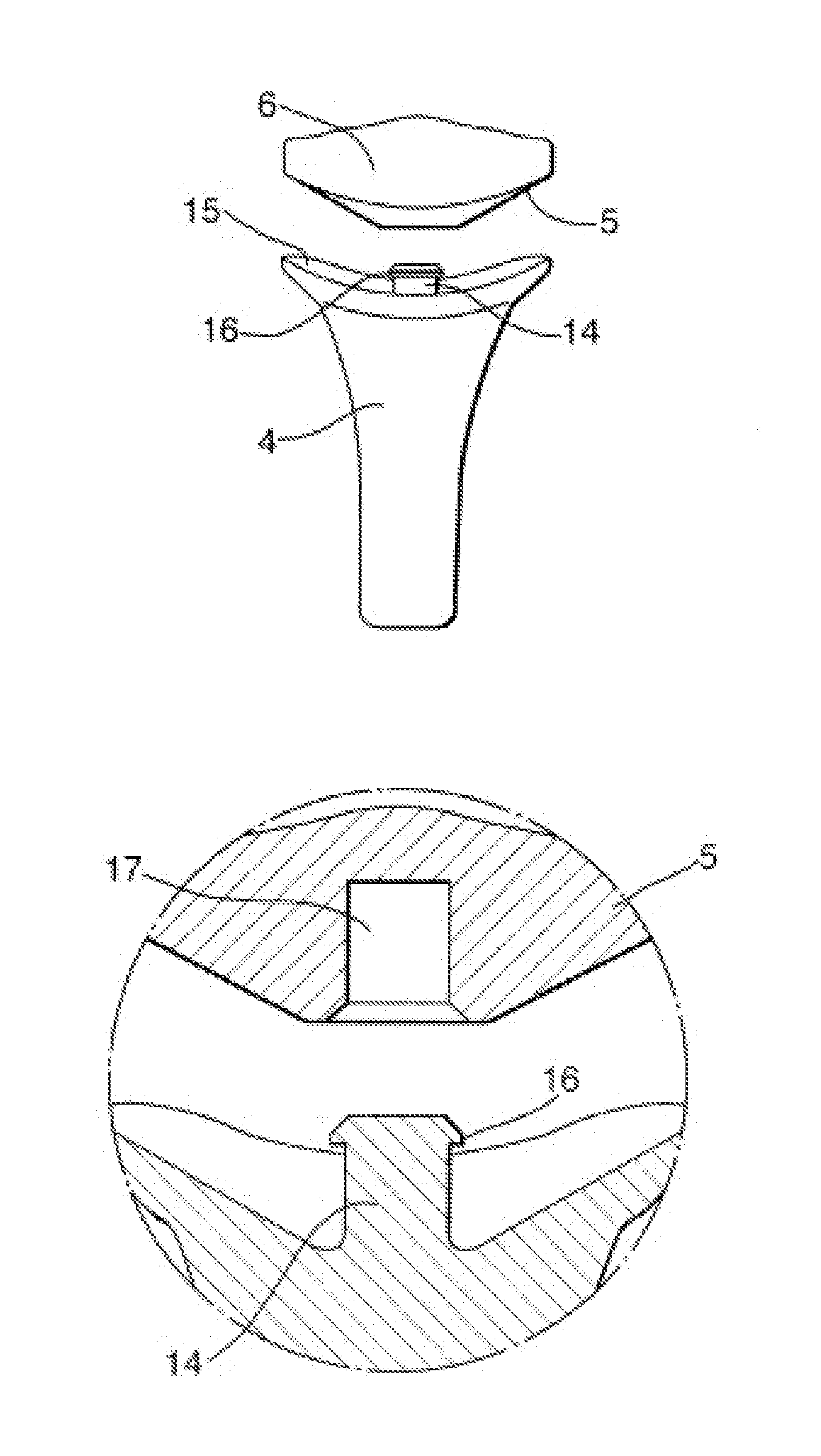
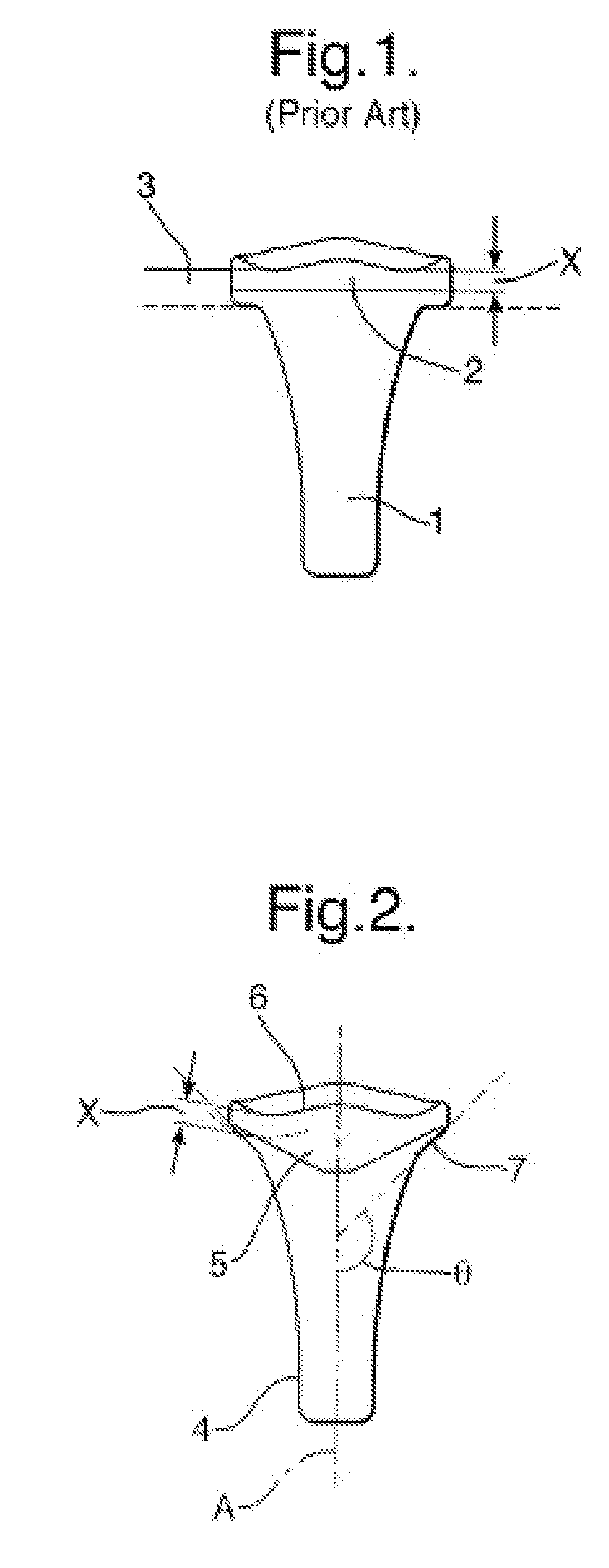
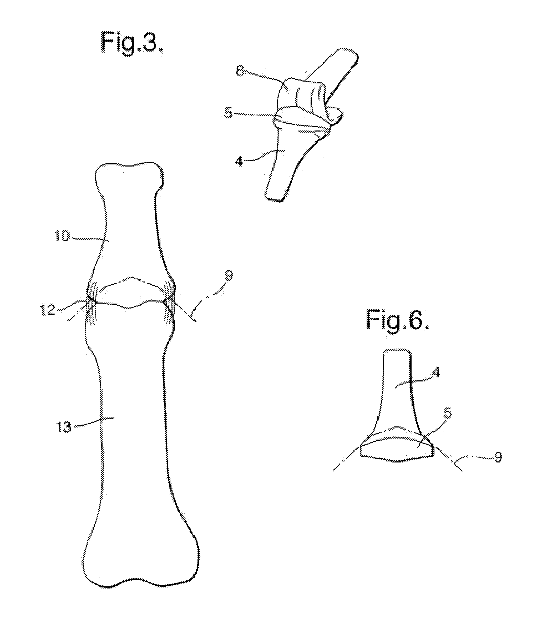
[0024]As illustrated in FIG. 2 the prosthetic component of the present invention comprises a stem portion 4 and a head portion 5. The head portion 5 has an upper surface 6 which in use provides an articulating surface. The undersurface 7 will, in use, bear on the bone into which the stem is implanted. The head component 6 extending from the stem portion 4 and is ramped away therefrom at an angle θ which is greater than 90° to the longitudinal axis A of the shaft. As in FIG. 1, X represents the minimum amount of material required under the articulating surface. It will be noted by comparison with the arrangement illustrated in FIG. 1 that a significant amount of bone may be retained in using the present invention having the generally conical profile.

[0025]In the preferred arrangement, the head portion is formed of biocompatible plastics material such as ultra high molecular weight polyethylene and the stem portion from a biocompatible metal such as cobalt chrome.

[0026]In use the uppe...


PUM


Abstract

A distal component for an interphalangeal prosthesis suitable for insertion into a proximal end of a distal phalangeal bone includes a stem portion shaped to be received within a surgically prepared bore in the proximal end of the distal bone. A head portion has an under-surface and an upper-surface, the under-surface of which in use will bear on the bone into which the stem is implanted.

Description

FIELD OF THE INVENTION[0001]The present invention relates to a prosthesis. More particularly it relates to a prosthesis for use in replacing the interphalangeal joint or the metacarpal-phalageal joint. For ease of reference the prosthesis of the present invention will be referred to as an “interphalangeal prosthesis” but it will be understood that the term will cover both prostheses for interphalangeal joints and those for the metacarpal-phalangeal joints whether in the hands or feet.BACKGROUND OF THE INVENTION[0002]The efficient functioning of the finger and / or toe joints is important to the well being and mobility of the human body. An interphalangeal joint is comprised by the distal end portion of a first phalange and the proximal end portion of the adjacent phalange. Similarly, the metacarpal-phalangeal joint is formed by the distal end of the metacarpus and the proximal end of the proximal phalange. In a normal healthy body these joints will be covered with articular cartilage....

Claims


Application Information

Patent Timeline
Patent Type & Authority Patents(United States)
IPC IPC(8): A61F2/32A61F2/30
CPCA61F2/4241A61F2002/4243A61F2002/4251
Inventor TRAIL, IAN ALEXANDERMATHIAS, RODERICK JOHN
Owner MATORTHO
Why Eureka
Try Eureka