Integrated electro-optical fluid rotary joint

a technology of electrooptical fluid and rotary joints, applied in the field of rotary joints, can solve the problem of not having a compound rotary joint to combine 3 media,

Active Publication Date: 2013-02-19
PRINCETEL
View PDF6 Cites 18 Cited by
  • Summary
  • Abstract
  • Description
  • Claims
  • Application Information

AI Technical Summary

Problems solved by technology

However, on commercial market, such a compound rotary joint to combine 3 media is not available yet.

Method used


Image

  • Integrated electro-optical fluid rotary joint
  • Integrated electro-optical fluid rotary joint
  • Integrated electro-optical fluid rotary joint

Examples


Embodiment Construction

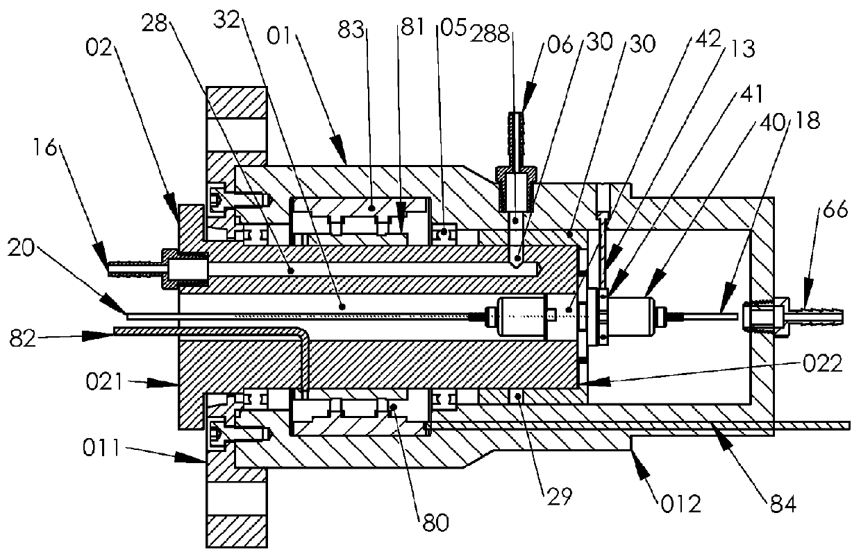
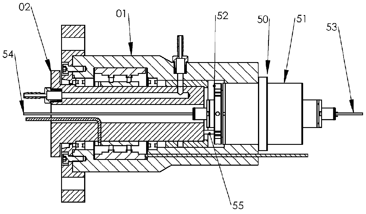
[0011]A detailed explanation of 2 preferred embodiments in the present invention with reference to FIG. 1, FIG. 2 and FIG. 3 is as follows.

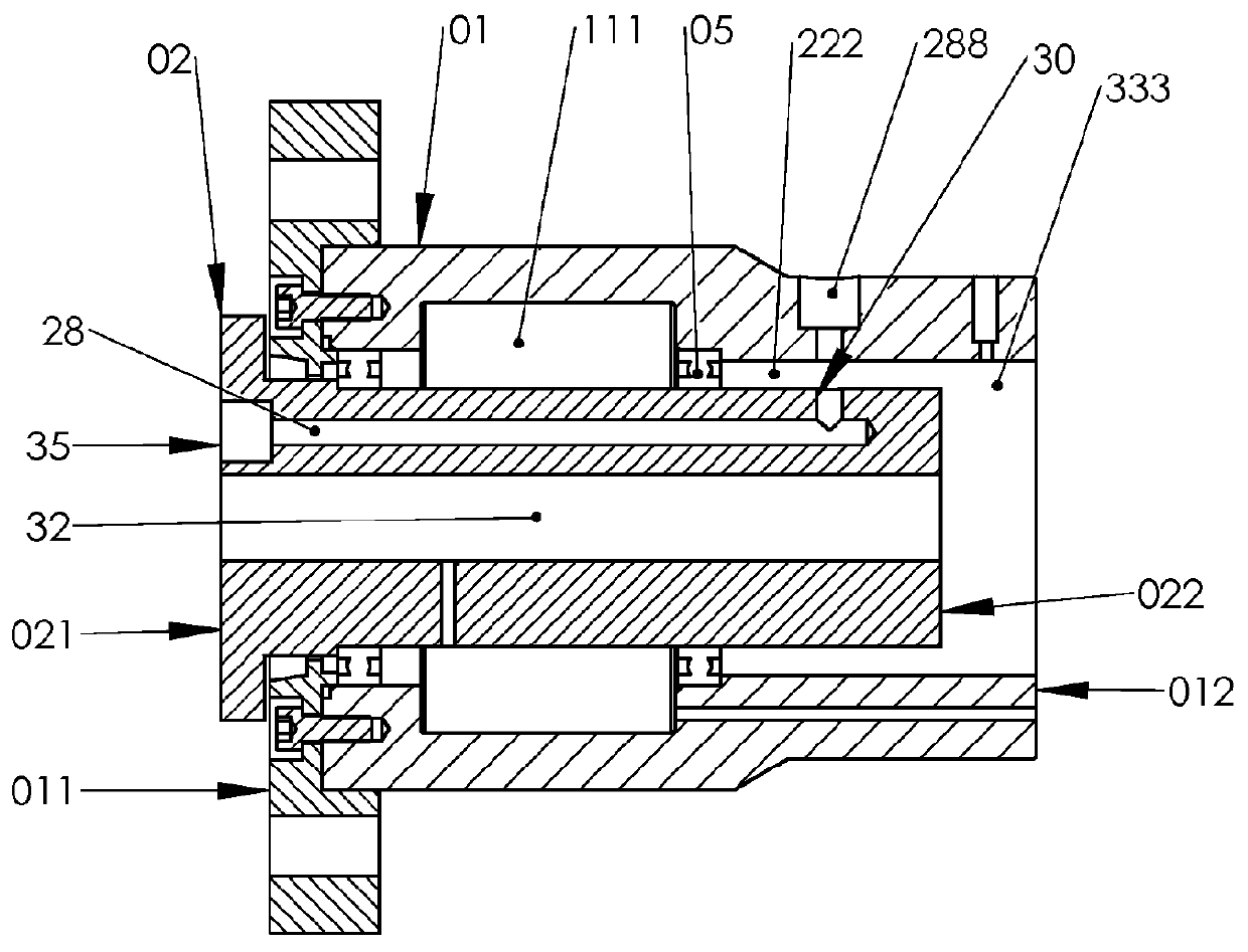
[0012]FIG. 1. shows the main configuration of the main stator 01 and main rotor 02 in the present invention. The main rotor 02 is rotatable relative to the main stator 01 through a pair of bearings 05. The main stator is a cylindrical part with an inner space. The main rotor 02 is also a cylindrical part with a central hole 32 and at least one off-centered hole 28. The main stator has two end surfaces: the first end surface 011 and second end surface 012. The main rotor 02 has two end surfaces: the first end surface 021 and second end surface 022. The annular space between the opposing peripheral surfaces of the main stator 01 and the main rotor 02 is divided into three portions along the axial direction: the front portion 111, the rear portion 333 and the middle portion 222. The off-centered hole 28 has first end opening 35 at the first end surf...


PUM


Abstract

An integrated electro-optical fluid rotary joint has been invented in which optical signals, electrical power, and/or signal(s), as well as fluids can be simultaneously transmitted across a common rotary-stationary interface between two relatively rotatable members for such applications, as a tethered aerostats, and tethered ROV. It consists of a main stator, a main rotor rotatable relative to said main stator. An electrical rotary joint, or slip ring, a fiber optical rotary joint, and a fluid rotary joint are integrated together on the main stator and main rotor. As a result, when the main rotor rotates relative to the main stator, optical signals, electrical power, and/or signal(s), as well as fluids from the main rotor can be transmitted to the main stator, and vise versa.

Description

BACKGROUND OF THE INVENTION[0001]The present invention relates generally to rotary joints involving electrical, optical and fluid aspects, and more particularly to apparatus for transferring optical signals, electrical power, and / or signal(s), as well as fluids across a common rotary-stationary interface between two relatively rotatable members.[0002]It is well known that the devices to transmit optical data between two independently rotational members are called fiber optical rotary joints. There are single channel, two channel and multi-channel fiber optical rotary joints. A typical fiber optical rotary joint consists of a fixed fiber collimator holder and a rotatable fiber collimator holder which are relatively rotatable each other to allow uninterrupted transmission of optical signals through the rotational interface from fiber collimators on any one of the holders to the fiber collimators on another holder.[0003]Electrical rotary joints, or electrical slip rings are electromech...

Claims


Application Information

Patent Timeline
Patent Type & Authority Patents(United States)
IPC IPC(8): G02B6/26
CPCG02B6/3604
Inventor ZHANG, HONGZHANG, BOYING BVIOLANTE, LOUIS D.
Owner PRINCETEL
Why Eureka
Try Eureka