Eureka AIR delivers breakthrough ideas for toughest innovation challenges, trusted by R&D personnel around the world.

Specialized glove apparatus

Inactive Publication Date: 2013-02-26
WELLS STEVEN D
View PDF46 Cites 3 Cited by
  • Summary
  • Abstract
  • Description
  • Claims
  • Application Information

AI Technical Summary

Benefits of technology

[0007]To attain this, the specialized glove apparatus provides a tool that is selectively worn and thereby immediately used as needed, without reaching, searching, or locating other tools. The apparatus guards a hand used for breaking glass and other such objects, and for cutting through various materials. The spike of the apparatus may be located on a reinforced panel that spreads the force exerted on the spike when used, thereby cushioning any blow to the hand. The spike is short with a wide base, in order to break glass and other such objects, and not merely pierce them. A user may, for example, ball his hand into a fist and use the heel of the hand, with spike, to shatter a window or windshield in order to rapidly extricate a victim from a dangerous auto.
[0008]The reinforced panel may be padded, semi-rigid, or even rigid, and may be comprised of various materials, such as steel, plasticized materials, and even composites. The reinforced panel may be ext

Problems solved by technology

Such situations call for tools at the ready, especially when hands and body are

Method used


Image

  • Specialized glove apparatus
  • Specialized glove apparatus
  • Specialized glove apparatus

Examples


Example

DETAILED DESCRIPTION OF THE DRAWINGS

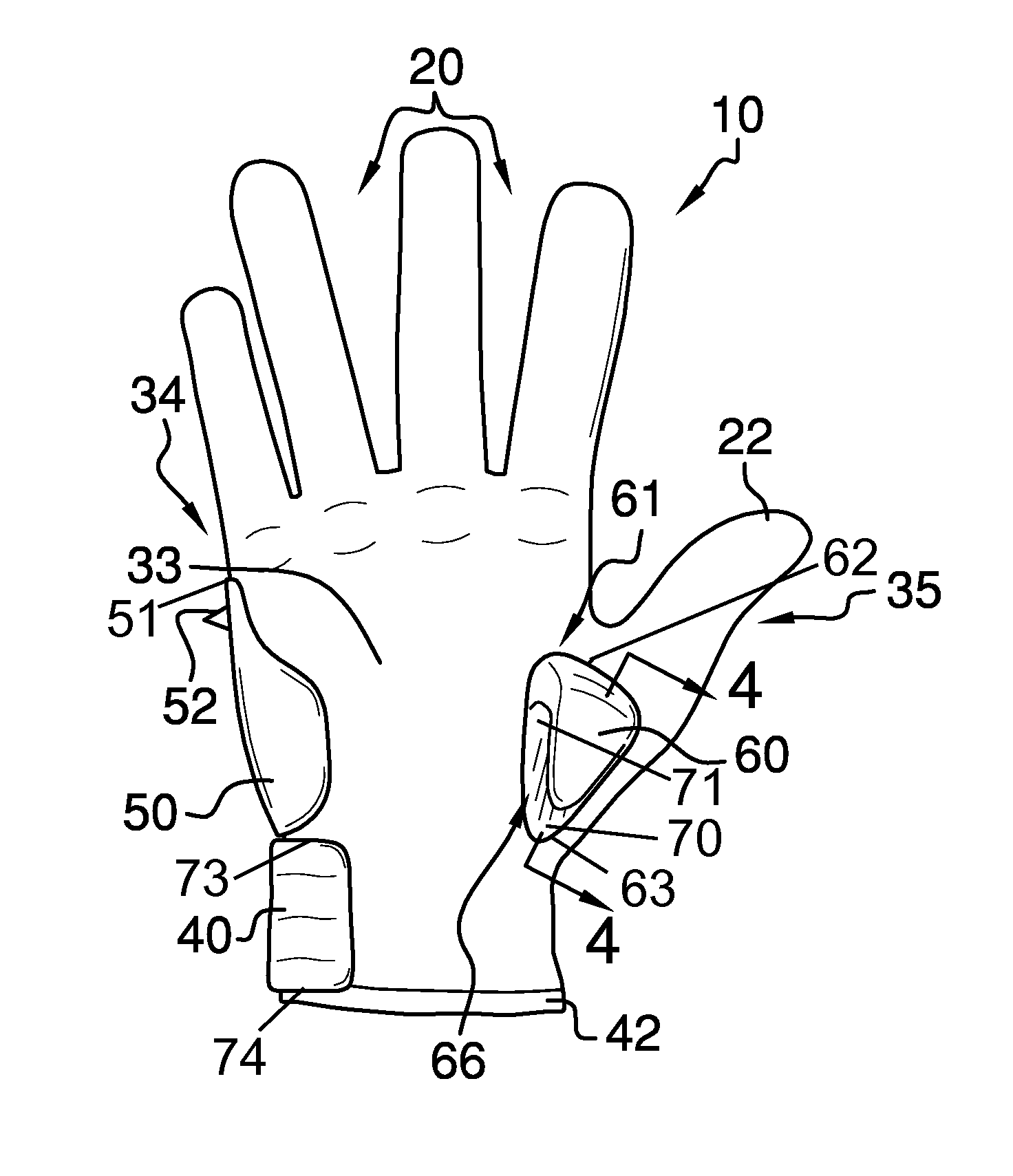
[0021]With reference now to the drawings, and in particular FIGS. 1 through 5 thereof, the principles and concepts of the specialized glove apparatus generally designated by the reference number 10 will be described.

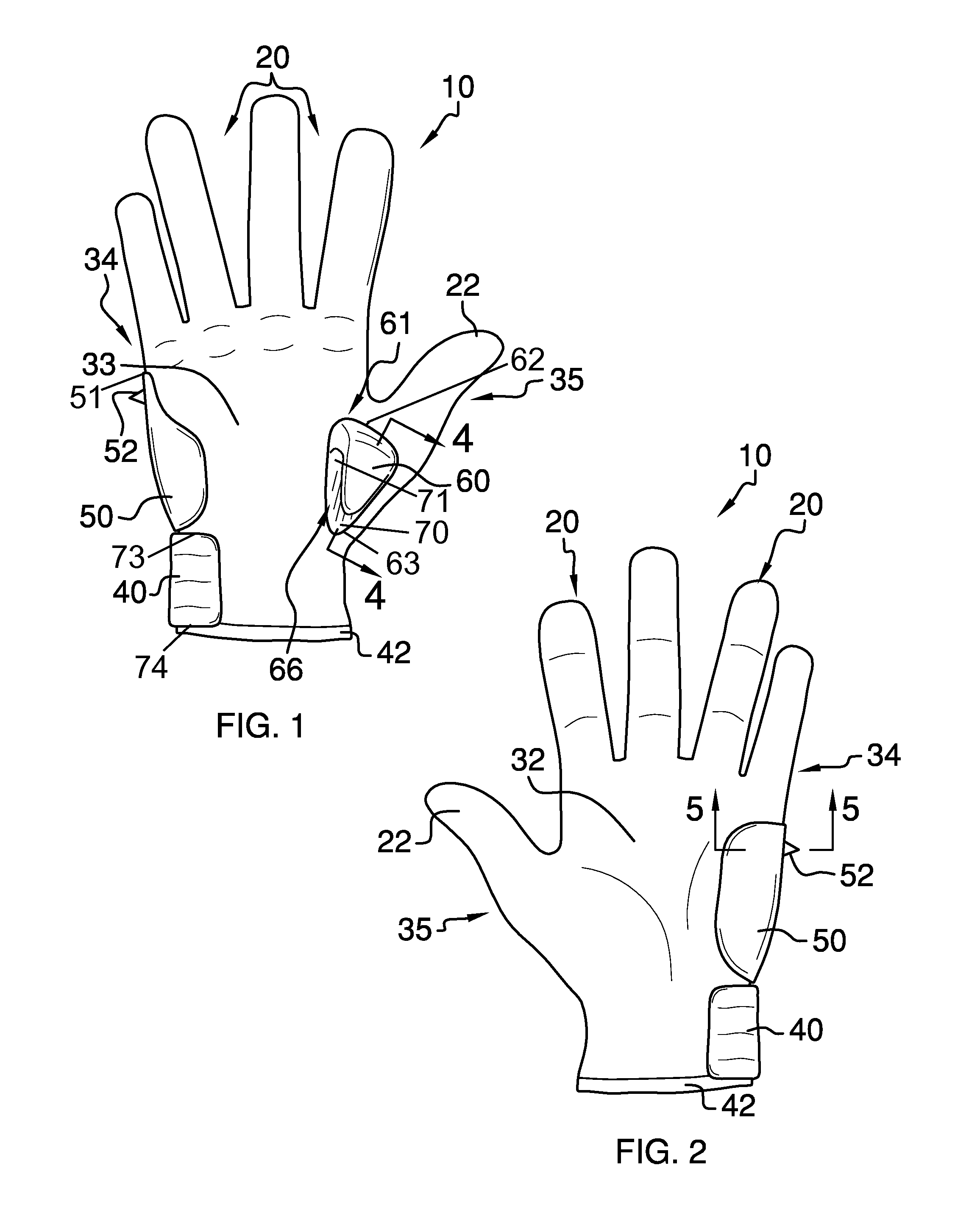
[0022]Referring to FIG. 1, the apparatus 10 partially comprises a plurality of fingers 20, a thumb 22, a thumb side 35, a finger side 34, and a backhand 33.

[0023]Referring to FIG. 2, the apparatus 10 further comprises a forehand 32 and a wristband 42. The wristband 42 is, in alternate designs, comprised of rigid and of elastic materials.

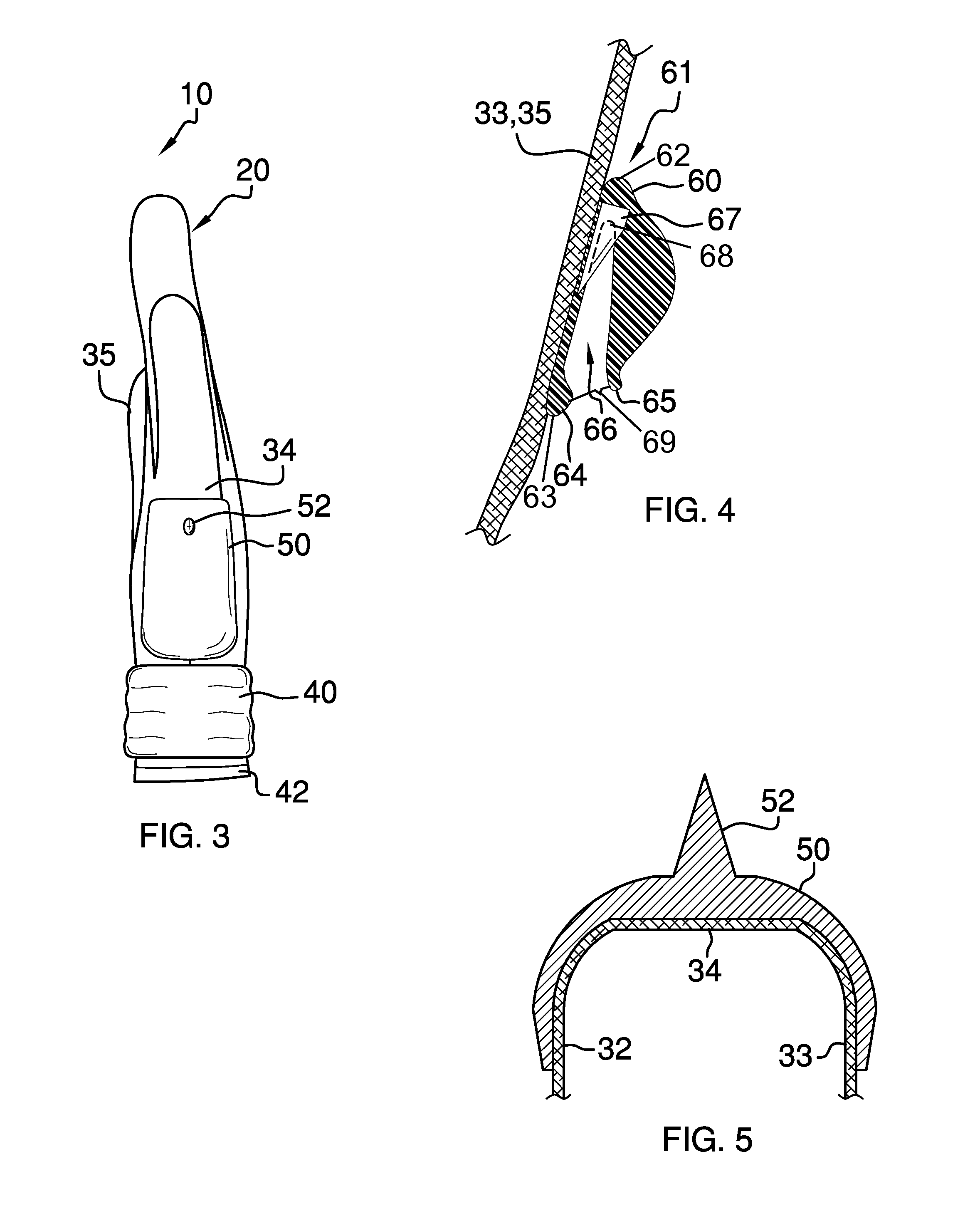
[0024]Referring to FIG. 3, the reinforced panel 50 is disposed on the finger side 34 below the fingers 20.

[0025]Referring to FIG. 5, the reinforced panel 50 is wrapped to include a part of the backhand 33 and the forehand 32.

[0026]Referring again to FIG. 3, the reinforced panel 50 begins proximal to the fingers 20. The abbreviated, substantially stubby cone-shaped spike 52 is disposed on the reinforced ...


PUM


Abstract

The specialized glove apparatus has a plurality of fingers, a thumb, a thumb side, a finger side, a backhand, a forehand, a wristband disposed most downwardly, a reinforced panel disposed on the finger side below the fingers, the reinforced panel beginning proximal to the fingers, an abbreviated, substantially stubby spike disposed upwardly and laterally on the reinforced panel, a cutter disposed on the backhand substantially below the thumb, the cutter comprising, a triangulated clam shape, an opened deep recess, a blade disposed completely within the deep recess, a fat lip guide disposed medially on the cutter, at a beginning of the deep recess, a thin upturn disposed laterally on the cutter, the thin upturn opposite the fat lip guide, across the deep recess, and a wrist pad disposed adjacent to the reinforced panel, the wrist pad extended to the wristband.

Description

CROSS-REFERENCE TO RELATED APPLICATIONS[0001]Not ApplicableFEDERALLY SPONSORED RESEARCH OR DEVELOPMENT[0002]Not ApplicableINCORPORATION BY REFERENCE OF MATERIAL SUBMITTED ON A COMPACT DISK[0003]Not ApplicableBACKGROUND OF THE INVENTION[0004]Experience in EMS and rescue and like activities has taught the importance of tools, especially tools that are quickly utilized in saving lives, where time is of dire criticality. Picture, for example, a rescue worker pulling a fire hose to douse a flaming car, and needing to access the interior of the car quickly in order to save a life. Such situations call for tools at the ready, especially when hands and body are already fully occupied and can only spare seconds or even fractions of a second. The need to break glass is often paramount in such extrication situations. The need to cut through materials such as seatbelts is often required. Such actions must often be performed instantaneously and, again, while typically fully occupied in other nee...

Claims


Application Information

Patent Timeline
IPC IPC(8): A41D19/00
CPCA41D19/01594
Inventor WELLS, STEVEN D.
Owner WELLS STEVEN D
Why Eureka
Eureka Blog
Learn More