Vehicle lamp

a technology for vehicles and lamps, applied in the field of vehicles, can solve the problems of increased manufacturing costs, increased components, and increased point light emissions from respective led light sources, and achieve the effect of increasing the number of components and reducing the cost of fabrication

Inactive Publication Date: 2013-02-26
KOITO MFG CO LTD
View PDF8 Cites 11 Cited by
  • Summary
  • Abstract
  • Description
  • Claims
  • Application Information

AI Technical Summary

Benefits of technology

[0007]One or more embodiments of the invention provide a vehicle lamp which can illuminate brightly a wide range around a periphery of a vehicle with an inexpensive configuration.

Problems solved by technology

However, according to the vehicle lamp shown in FIG. 11 or in JP-A-2006-164908, the same number of substrates as the number of light sources are needed to change the orientations of the LED light sources, which increases the number of components, leading to a problem that the fabrication costs are increased.
In addition, since the LED light sources are arranged in a horizontal direction, a depth of the lamp is increased, and there is caused a drawback that point light emissions from the respective LED light sources tends to become visible from the outside of the vehicle lamp.
In the vehicle lamp of JP-A-2004-001710, although the substrate can be commonized, since the plurality of light sources are both oriented to the front of the vehicle, there is caused a problem that the side and rear of the vehicle become relatively dark.

Method used


Image

  • Vehicle lamp
  • Vehicle lamp
  • Vehicle lamp

Examples


Embodiment Construction

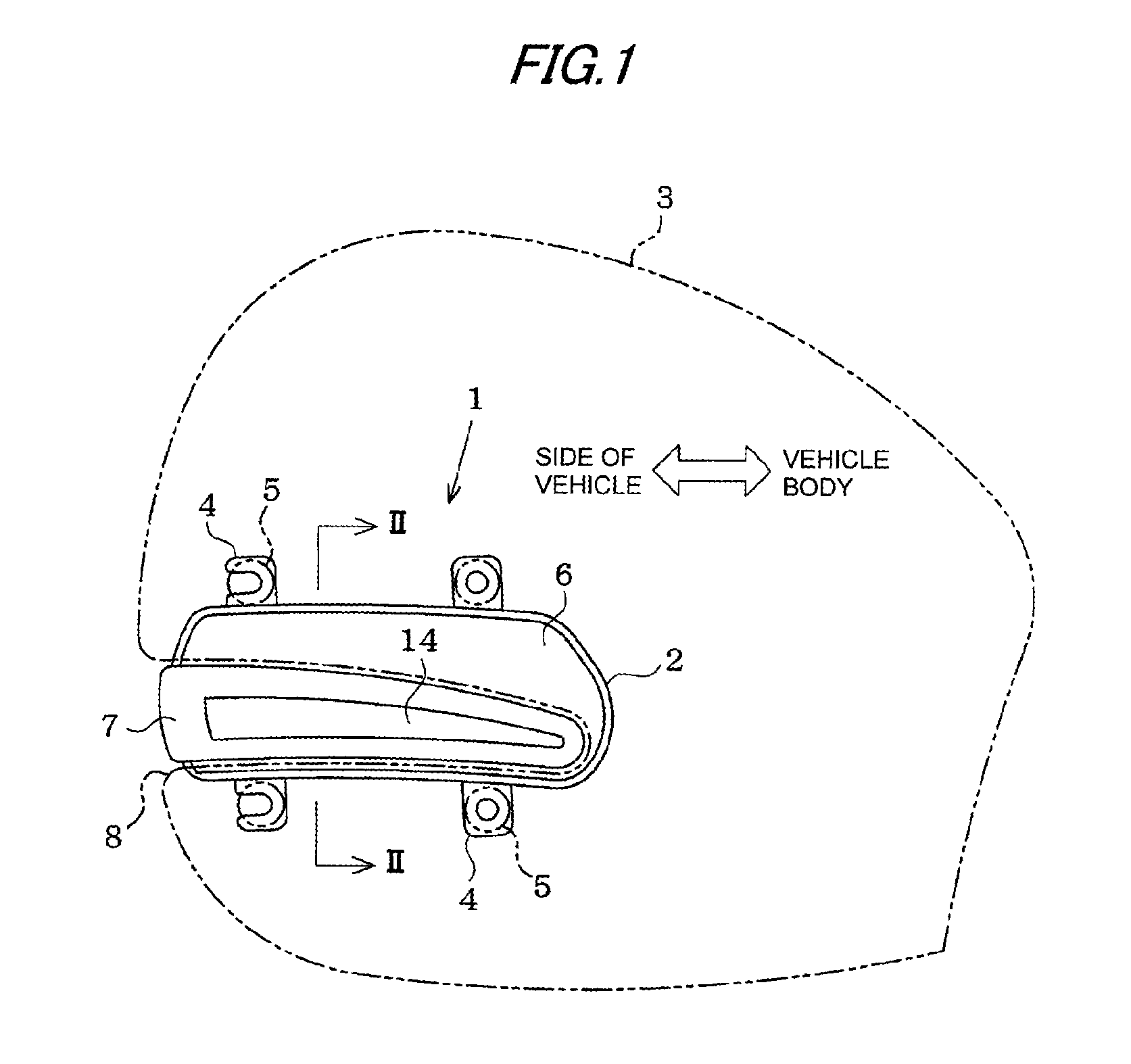
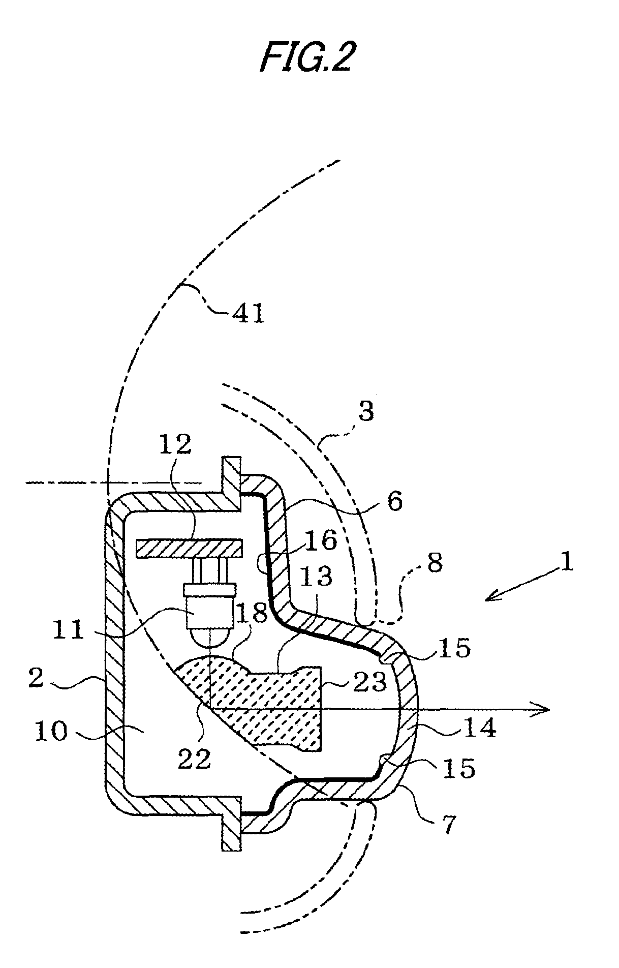
[0021]An exemplary embodiment of the invention will be described based on the accompanying drawings. In the exemplary embodiment, a vehicle lamp of the invention is embodied into a side turn signal lamp of a motor vehicle. As shown in FIG. 1, a body 2 of the side turn signal lamp 1 is placed in an interior of a mirror housing 3 and is fixed in place by mounting pieces 4 by employing screws. An outer cover 6 is placed on a front side of the lamp body 2 and is held on the mirror housing 3 via a retainer (whose illustration is omitted). An exposing portion 7 having a laterally elongated protuberant shape is formed on the outer cover 6 so as to be exposed from an opening portion 8 in the mirror housing 3.

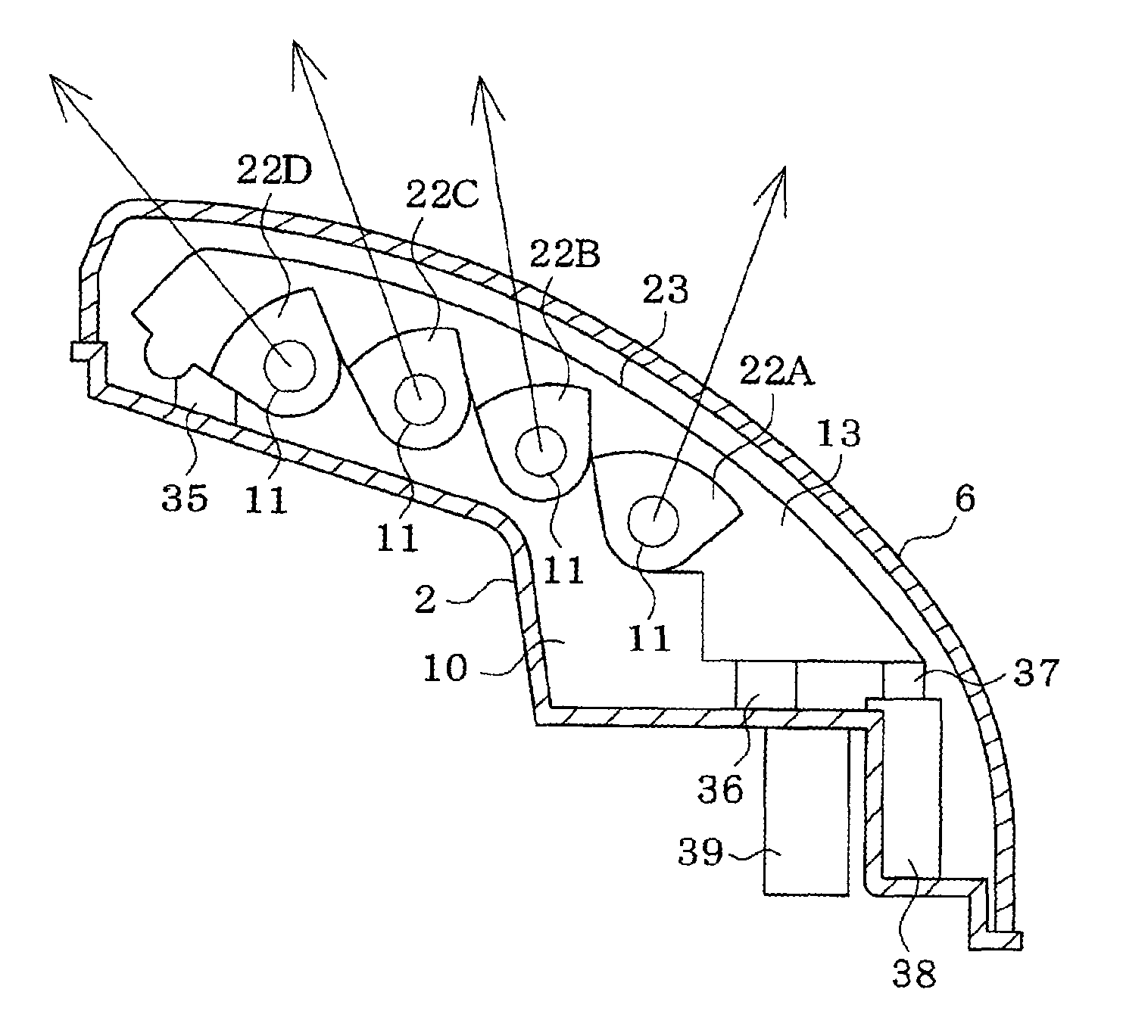
[0022]As shown in FIG. 2, LED light sources 11, a substrate 12 and a light guiding lens 13 are disposed within a lamp chamber defined between the lamp body 2 and the outer cover 6. The LED light sources 11 are mounted on the substrate 12 so as to be oriented downwards. The light guiding...


PUM


Abstract

In a vehicle lamp (1), a plurality of LED light sources (11) are arranged on a common substrate (12). A light guiding lens (13) elongated in a direction in which the LED light sources (11) are aligned is provided. A plurality of reflecting sections (22) are provided on the light guiding lens (13). The reflecting sections (22) are configured to individually reflect incident lights from the respective LED light sources (11) to a periphery of a vehicle. Respective directions of the reflecting sections (22) are made to differ in accordance with positions of the corresponding LED light sources (11).

Description

BACKGROUND OF THE INVENTION[0001]1. Field of the Invention[0002]The present invention relates to a vehicle lamp which illuminates a predetermined range on a periphery of a vehicle with light from a plurality of LED light sources.[0003]2. Related Art[0004]FIG. 11 shows a side turn signal lamp 51 which relates to the invention. The lamp 51 is provided with a lamp body 53 installed within a housing 52 of a door mirror (which is an outside rearview mirror on a front side door) and an outer cover 54. A plurality of LED light sources 56 and a plurality of substrates 57 of the same number with the light sources are disposed within a lamp chamber 55 defined by the lamp body 53 and the outer cover 54. The substrates 57 are held in different orientations by holders 58, so that a wide range including the front, side and rear of the vehicle is illuminated with light from the plurality of light sources 56.[0005]JP-A-2006-164908 discloses a vehicle lamp which includes an inner lens for covering a...

Claims


Application Information

Patent Timeline
Patent Type & Authority Patents(United States)
IPC IPC(8): F21V7/00F21W107/10
CPCB60Q1/2665B60R1/1207F21S48/215F21S48/2225F21S43/14F21S43/235F21S43/15F21S43/315
Inventor ISHIKAWA, TOMOMIKAZAOKA, SHIGEHIKO
Owner KOITO MFG CO LTD
Why Eureka
Try Eureka