
Electrode catheter for interventional use

a technology of electrode catheter and electrode electrode, which is applied in the direction of external electrodes, internal electrodes, therapy, etc., can solve the problem of still too little effect for the requirements, and achieve the effects of reducing the energy absorbed by the antenna, increasing the resistance of the supply line, and reducing the sheath resistan

Inactive Publication Date: 2013-02-26
BIOTRONIK SE & CO KG
View PDF15 Cites 22 Cited by
  • Summary
  • Abstract
  • Description
  • Claims
  • Application Information

AI Technical Summary

Benefits of technology

[0015]Starting from the problems described at the beginning, the present invention is based on the object of refining an electrode for interventional purposes in such a way that it may be placed even in radiation fields of MR diagnostic devices without relevant risk to the wearer in a constructively simple way. In particular, simple and cost-effectively producible materials are to be used, which allow a targeted effective and sufficient worsening of the properties of the electrode in regard to its antenna characteristic, without current concentrations and corresponding excess heating being able to occur at electrode poles, in particular around the tip of the electrode.
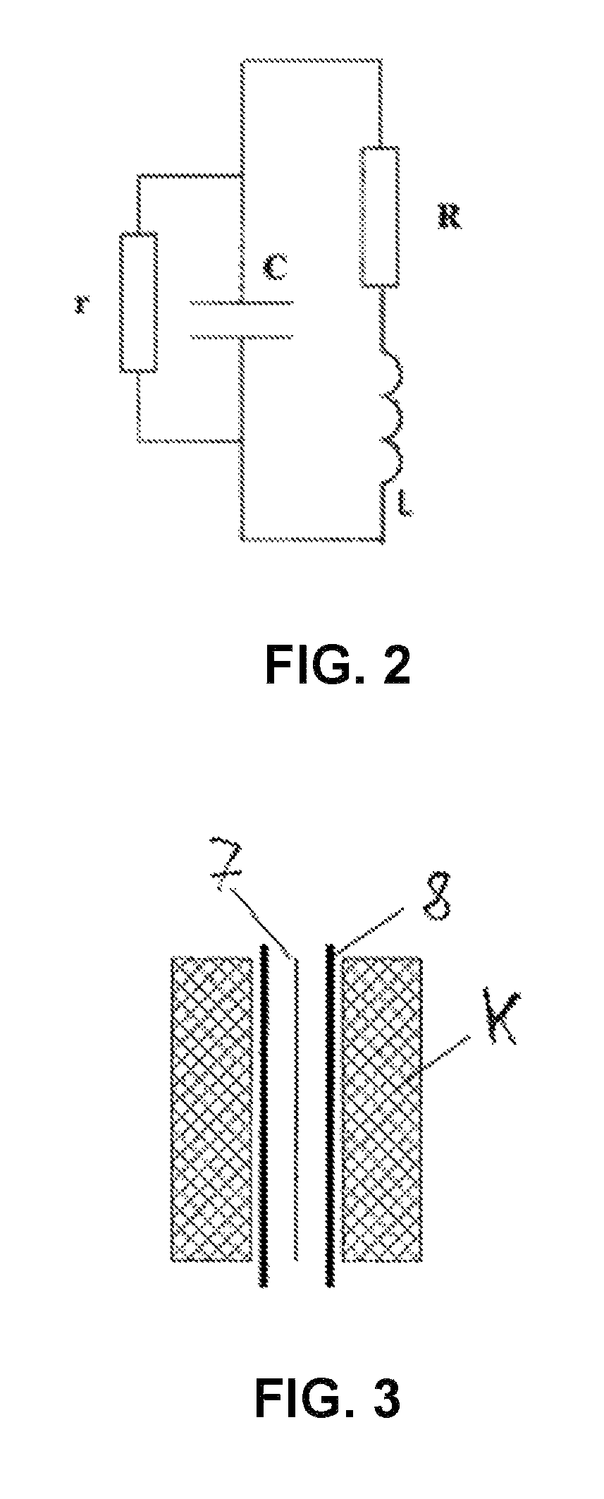
[0017]According to a first aspect of the present invention, the concentration of conductive particles in the first material is set in such a way that the conduction resistance R increases with rising frequency of an incident electromagnetic wave. According to a further aspect, the concentration of conductive particles in the second material is set in such a way that the sheath resistance r decreases with rising frequency of an incident electromagnetic wave. These aspects have the advantage that, in a simple way and using materials to be produced simply, the property that the effect of radiation fields of magnetic resonance diagnostic devices on the electrode may be almost completely compensated for may thus be exploited effectively.
[0018]A further object is seen as providing a production method for an electrode for interventional purposes according to the present invention, which offers secure MR compatibility of the line.
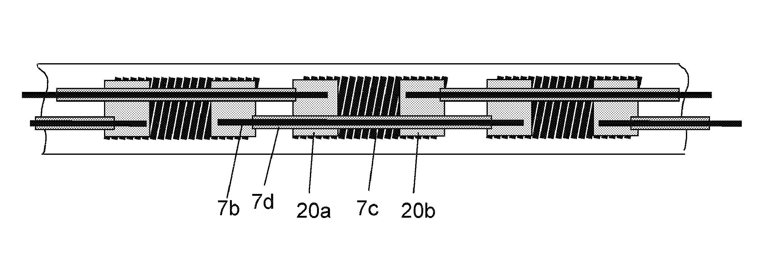
[0020]As will be clear from the later consideration of the background of the present invention in the scope of the description of exemplary embodiments, according to the present invention, the quality of the oscillating circuit which the electrode forms together with the body as the antenna is reduced enough that on one hand the energy absorbed by the antenna is reduced and on the other hand the losses are distributed in the overall formation of electrode conductor / insulation / body in such a way that excess current concentration does not occur at specific points. This may be achieved by increasing the line resistance R of the supply line, by reducing its sheath resistance r, or by both.
[0021]The essential advantage of reducing the quality of the antenna in relation to a band filter is that the mode of operation is independent of the resonance frequency of the antenna and of the frequency of the incident electromagnetic alternating field, i.e., the energy absorbed by the antenna, is reduced by the quality factor at all frequencies. In this way, the achievement of the object according to the present invention works equally in various MR devices having various operating frequencies.

Problems solved by technology

The ohmic conductivity also surprisingly increases with the frequency for the pure polymer, i.e., not doped with carbon nanotubes (CNT) (pure polycarbonate was studied), but the effect is still too little for the requirements here, however.

Method used


Image

  • Electrode catheter for interventional use
  • Electrode catheter for interventional use
  • Electrode catheter for interventional use

Examples


Embodiment Construction

[0035]Firstly, the following fundamental statements on the oscillation behavior of antenna circuits are to be given on the background of the present invention:

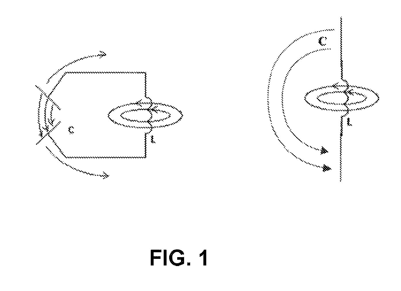
[0036]If a preferably elongate electrical conductor is located in the room, this conductor acts as an antenna for electromagnetic radiation which floods through the room. The antenna converts the free space wave into a line wave, through which antenna currents flow. This situation exists, for example, if a patient having implanted cardiac pacemaker electrodes is subjected to an electromagnetic alternating field. The currents which arise in the electrode supply line acting as an antenna are conducted into the body at the contact points to the tissue and essentially converted into heat there. Depending on the strength of the electromagnetic alternating field, the extent of the heating may be hazardous to the patient. Alternating fields of hazardous strengths to pacemaker wearers occur—as noted—in MR tomographs, for example.

[0037...


PUM


Abstract

An electrode for interventional purposes, such as a cardiac pacemaker, neurostimulation, or ICD electrode, comprises an elongate electrode body (6), at least one electrode pole (5) in the area of the distal end (4) of the electrode body (6) for delivering an intervention pulse, at least one supply line (7) running in the electrode body (6) to the at least one electrode pole (5), and an electrode sheath (8) for insulating the supply line (7). The first and / or second material is produced in such a way that it contains conductive particles embedded in a polymer matrix in a concentration which is greater than or equal to the percolation threshold.

Description

[0001]This application takes priority from German Patent Application DE 10 2006 054 620.2 filed 17 Nov. 2006 and German Patent Application DE 10 2007 022 333.3, filed 12 May 2007, the specifications of which are hereby incorporated herein by reference.BACKGROUND OF THE INVENTION[0002]1. Field of the Invention[0003]The present invention relates to an electrode for interventional purposes, such as a pacemaker or ICD electrode or an electrophysiological catheter, as is used, for example, with pacemakers, defibrillators, neurostimulators, and in procedures of electrophysiology (EP).[0004]2. Description of the Related Art[0005]Electrodes of this type are known to have an elongate electrode body having a distal end and a proximal end. At least one active electrode pole for delivering an intervention pulse is provided in the area of the distal end. This electrode pole is designed, for example, as a tip electrode pole situated directly at the distal end, as a ring pole placed at a distance ...

Claims


Application Information

Patent Timeline
Patent Type & Authority Patents(United States)
IPC IPC(8): A61N1/05
CPCA61N1/056A61N2001/086A61N1/3718A61N1/086
Inventor FLACH, ERHARDGEISTERT, WOLFGANGMAXFIELD, MICHELLEWEISS, INGOFRIEDRICH, MICHAEL
Owner BIOTRONIK SE & CO KG
Learn More