
Aromatic amine derivative and organic electroluminescence device using the same

a technology of organic electroluminescent devices and amine derivatives, which is applied in the direction of luminescent compositions, organic chemistry, luminescent compositions, etc., can solve the problems of low luminance, low efficiency of light emission, and remarkable deterioration of conventional organic el devices, so as to achieve sufficient luminance of light emitted, high efficiency of light emission, and free from deterioration in properties

Inactive Publication Date: 2010-01-05
IDEMITSU KOSAN CO LTD
View PDF15 Cites 15 Cited by
  • Summary
  • Abstract
  • Description
  • Claims
  • Application Information

AI Technical Summary

Benefits of technology

The aromatic amine derivatives enable organic EL devices to exhibit high luminance and efficiency with prolonged lifespan, even under low voltage, and maintain performance over time, making them suitable for display applications.

Problems solved by technology

The conventional organic EL devices require a high drive voltage and exhibit a low luminance and a low efficiency of light emission as compared to inorganic light emitting diodes.
In addition, the conventional organic EL devices suffer from remarkable deterioration in properties and, therefore, are still practically unusable.
However, in this technique, a luminance obtained by using the material is as low as 1650 cd / m2, for example, at a current density of 165 mA / cm2, and an efficiency of light emission thereof is very low, i.e., only 1 cd / A, which is practically unusable.
However, the organic EL devices still fail to exhibit a sufficiently long life and, therefore, further improvement of these devices has been required.
However, in these techniques, the wavelength of emission spectra is too long owing to a conjugated structure of the styryl compound, resulting in poor color purity of light emitted.
The device is excellent in efficiency of light emission but still fails to show a sufficiently long life and, therefore, further improvement of the device has been required.

Method used


Image

  • Aromatic amine derivative and organic electroluminescence device using the same
  • Aromatic amine derivative and organic electroluminescence device using the same
  • Aromatic amine derivative and organic electroluminescence device using the same

Examples


synthesis example 1

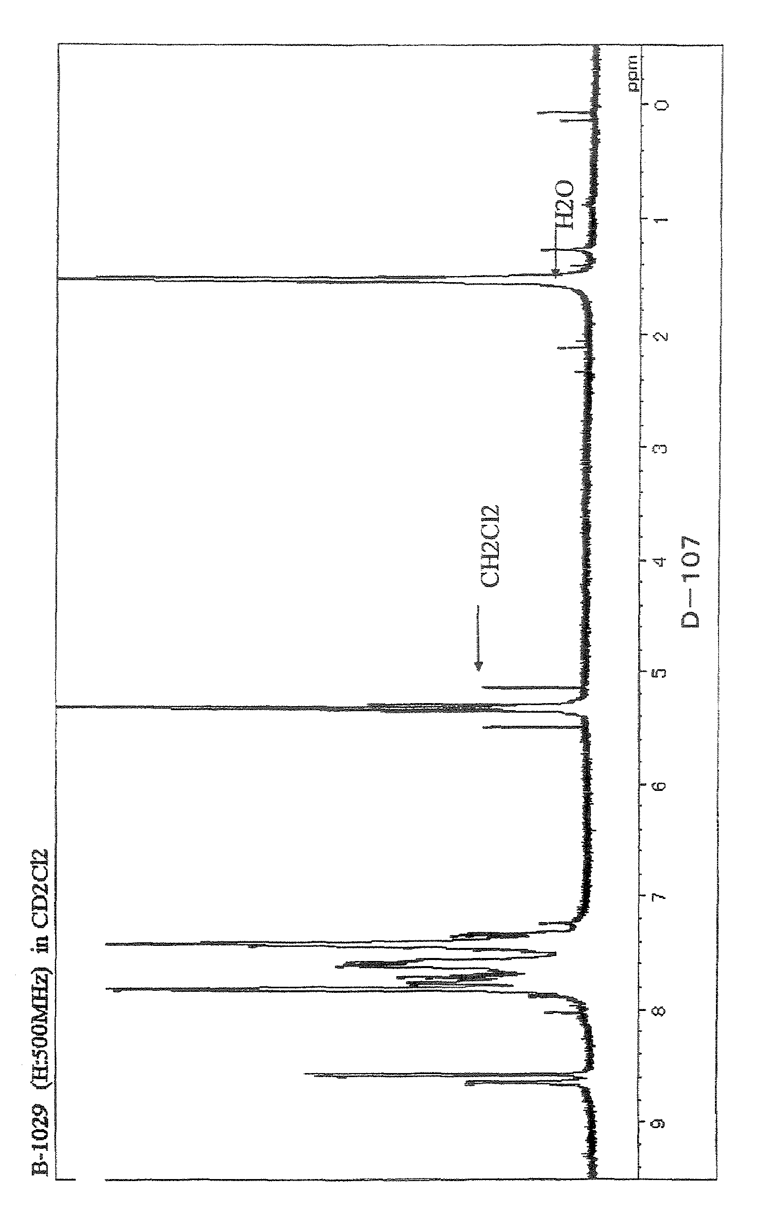
Synthesis of Compound (D-107)

(1) Synthesis of 3,4-bis[(trimethylsilyl)oxy]-1,6-bis(m-methoxybenzyl)-3-hexene

[0098]Under an argon gas flow, 73 g (3.18 mol) of sodium and 2 L of toluene were charged into a 5 L glass flask equipped with a condenser, and then heated to 110° C. to melt the sodium. Successively, 206 g (1.06 mol) of methyl 3-(m-methoxyphenyl)propionate and 346 g (3.18 mol) of trimethylsilyl chloride were added to the flask, and the contents of the flask were stirred at 110° C. for 20 h. After completion of the reaction, the precipitated inorganic salts were separated from the reaction solution by filtration. The organic layer thus separated was washed with 1 L of water four times and then dried with magnesium sulfate. The resultant dried product was concentrated under reduced pressure to obtain a crude product. The thus obtained crude product (210 g) was directly used in the subsequent reaction.

(2) Synthesis of 2,8-dimethoxy-5,6,11,12-tetrahydrochrysene

[0099]Under an argon...


PUM

PropertyMeasurementUnit
current densityaaaaaaaaaa
luminanceaaaaaaaaaa
work functionaaaaaaaaaa

Abstract

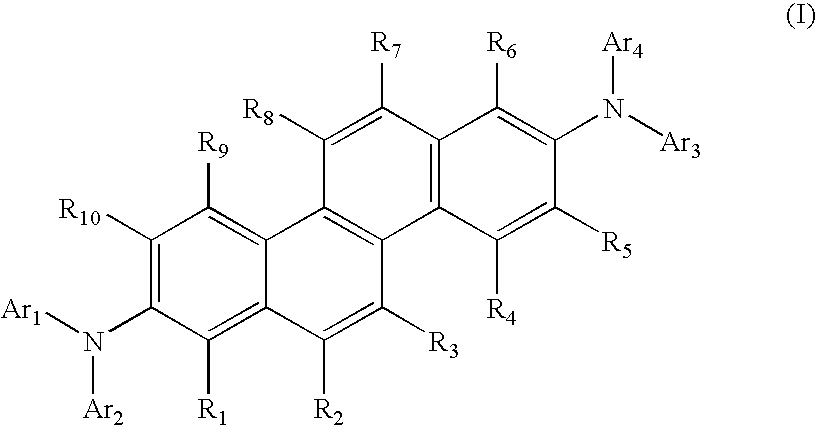
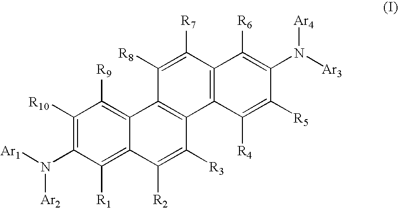
The present invention relates to aromatic amine derivatives having a specific structure; and organic electroluminescent devices comprising a cathode, an anode and one or plural organic thin film layers including at least a light emitting layer which are sandwiched between the cathode and the anode wherein at least one of the organic thin film layers contains the above aromatic amine derivatives in the form of a single substance or a component of a mixture. There are provided the organic electroluminescent devices exhibiting a long life and a high efficiency of light emission which are capable of emitting a blue light having a high color purity, as well as the aromatic amine derivatives capable of realizing such organic electroluminescent devices.

Description

TECHNICAL FIELD[0001]The present invention relates to aromatic amine derivatives and organic electroluminescent devices using the same, and more particularly to organic electroluminescent devices which exhibit a high efficiency of light emission and are capable of emitting a blue light having a high color purity, as well as aromatic amine derivatives capable of realizing such electroluminescent devices.BACKGROUND ART[0002]The organic electroluminescent (EL) devices made by using organic substances have been expected to be applied to production of large area full-color display devices of a solid light emission type at low costs, and have been intensively developed. In general, the organic EL devices are constituted from a light emitting layer and a pair of counter electrodes between which the light emitting layer is sandwiched. In the organic EL devices, when an electric field is applied between the electrodes, electrons are injected from a cathode into the light emitting layer, wher...

Claims


Application Information

Patent Timeline
Patent Type & Authority Patents(United States)
IPC IPC(8): C07C211/54
CPCC07C211/61C09K11/06C09K2211/1007C09K2211/1011C09K2211/1014C09K2211/1029C09K2211/1044C09K2211/1096Y10S428/917H10K85/622H10K85/626H10K85/633H10K85/615H10K50/11H10K85/631
Inventor FUNAHASHI, MASAKAZU
Owner IDEMITSU KOSAN CO LTD
Learn More