Strap attachment device

a technology of straps and clips, which is applied in the direction of fastening devices, safety belts, gymnastic exercise, etc., can solve the problems of inability to adjust and lock, large distance between the cord and the bar, and the length of the strap that extends from either side of the metal bar is not fixed

Active Publication Date: 2013-03-05
LIFELINE PROD LLC
View PDF42 Cites 23 Cited by
  • Summary
  • Abstract
  • Description
  • Claims
  • Application Information

AI Technical Summary

Benefits of technology

[0009]Returning to FIG. 1, a cam lever 126 is located at the opening 106 of the lower body end 102. FIGS. 3 and 4 show that cam lever 126 includes a lower face 128 and an opposing handle 130, with a bearing 132 located therebetween. The lower face 128 of the cam lever 126 preferably has an irregular surface (such as a toothed, ridged, or bumpy surface) to enhance gripping of a strap. Bearing 132 is preferably cylindrical, although other shapes may be used as well.
[0012]Referring to FIG. 3, the cam hook device preferably includes gate 144 (to enhance safety and stability) and a fixed end 146. The fixed end 146 attaches to the main body 100, and is oriented such that the gate 144 protrudes from the lower body end 102 toward the upper body end 104. The gate 144, which is preferably flexible, helps prevent the cam hook device from separating from an object on which the upper body end 104 is hooked.
[0016]Such a design offers many advantages. For example, combining the hook 122 of the upper body end 104 with the cam lever 126 and adjustable strap 200 of the lower body end 102 into one device reduces part count, reducing cost and improving usability. Integrating hook 122 and cam lever 126 in one device also positions the strap 200 closer to the object on which the upper body end 104 hooks, allowing a greater range of motion during exercises.

Problems solved by technology

Such hanging or looping, however, does not generally anchor the strap's position around the object, so the length of the strap that extends from either side of the metal bar is not fixed.
U.S. Pat. No. 6,267,711 to Hinds incorporates a multi-part mechanism for attaching an elastic cord to a bar, but the mechanism has: (i) a high part count; (ii) an inability to adjust and lock the position of the cord along the mechanism; and (iii) a large distance between the cord and the bar, limiting the range of motion.
Conventional strap attachment devices with high part counts tend to be costly and difficult to use.
Additionally, strap attachment devices that do not minimize the distance between the strap and an object to be linked with the strap limit the range of motion achievable for activities such as exercise.

Method used


Image

  • Strap attachment device
  • Strap attachment device
  • Strap attachment device

Examples


Embodiment Construction

[0023]It should be understood that various terms referring to orientation and position are used throughout this document—e.g., “upper” (as in “upper body end” or “upper hole”), “below” (as in “below the opening”), and “toward” (as in “toward the upper body end”)—and that such terms are relative rather than absolute. Such terms should be regarded as words of convenience, rather than limiting terms.

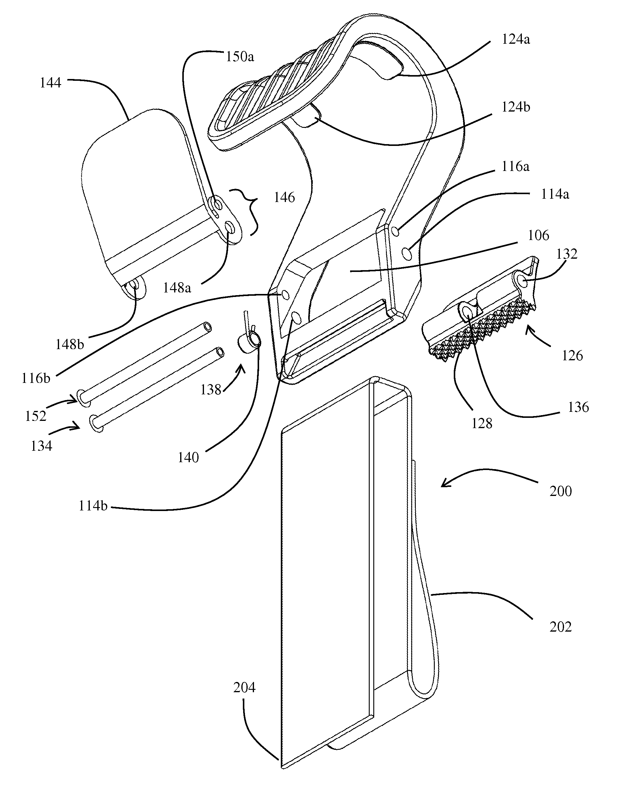
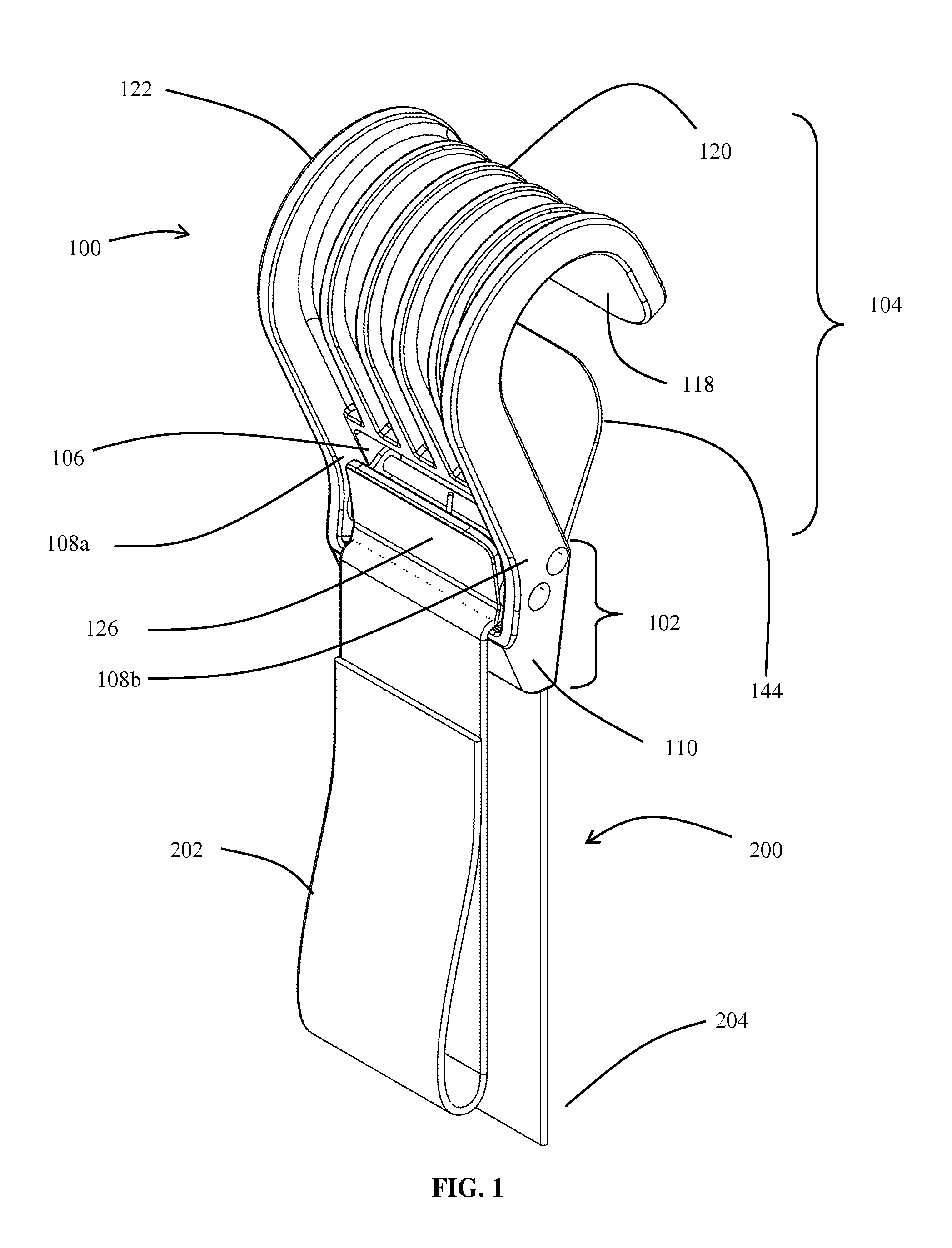
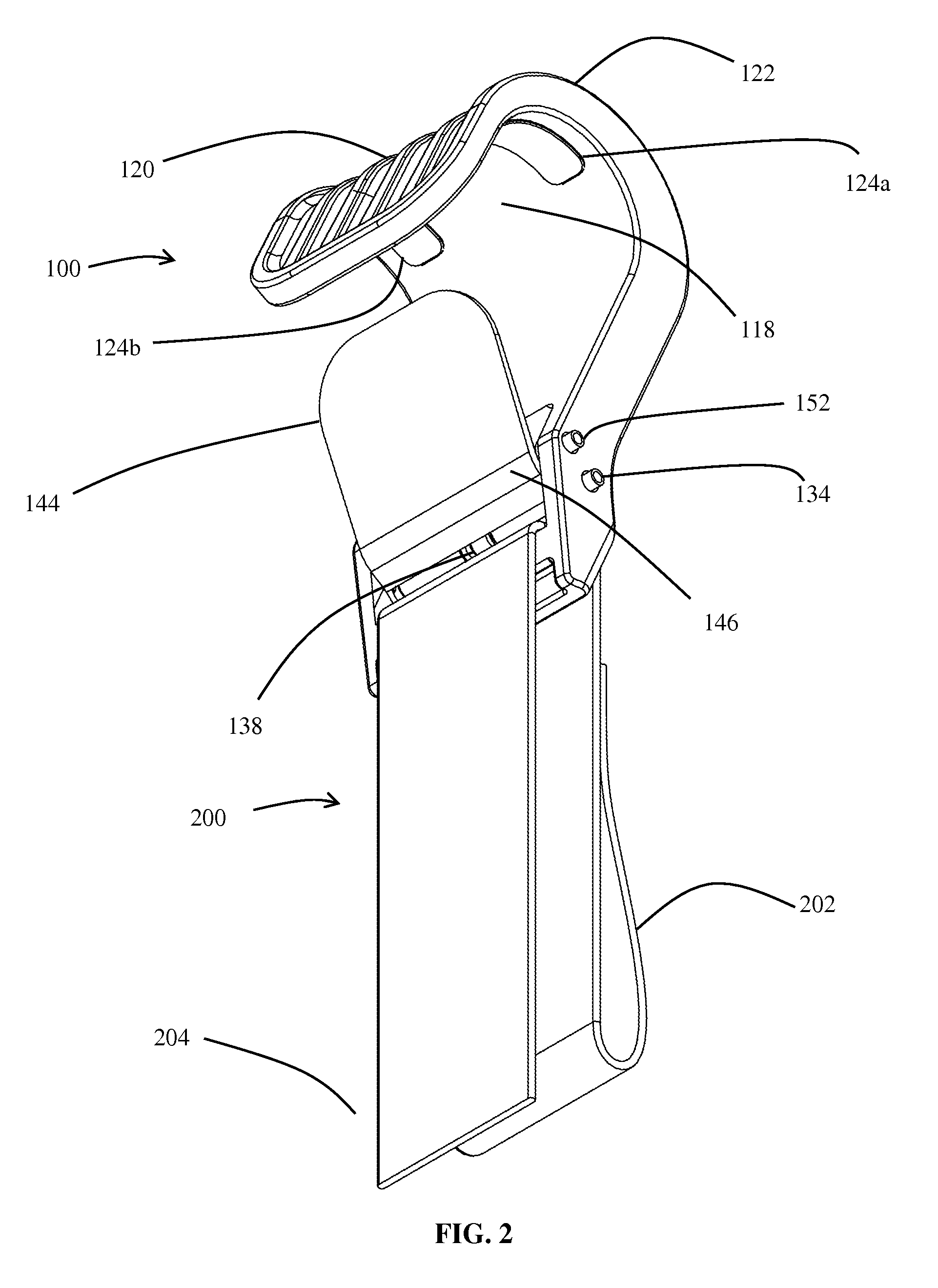
[0024]Continuing the discussion in the above Summary of the Invention section, FIG. 1 depicts an exemplary cam hook device that includes lower body end 102 and upper body end 104 extending upwards therefrom. The lower body end 102 and the upper body end 104 may be separately manufactured and affixed together to form the main body 100, or the main body 100 can be manufactured as a one structure. Moreover, the lower body end 102 may be constructed using a different material than the upper body end 104. One end may be constructed using, for example, a plastic or composite, while the other end ...


PUM


Abstract

A strap attachment device includes a main body with a lower body end that has an opening suited for a strap. Based on its position, a cam lever at the opening of the lower body end holds or releases the strap, permitting adjustment of the length of the strap that enters the opening. Extending upward from the lower body end is an upper body end that is curved into a hook or any other shape appropriate for connection to an object. A flexible or translatable gate may extend from the main body so as to prevent the upper body end from inadvertently becoming detached from the object. Slip-resistance on the upper body end resists slippage between the upper body end and the object during side-to-side movements. Ends of the strap may include a loop or handle or connect to other devices.

Description

CROSS-REFERENCE TO RELATED APPLICATION[0001]This application claims priority under 35 USC §119(e) to U.S. Provisional Patent Application 61 / 256,360 filed Oct. 30, 2009, the entirety of which is incorporated by reference herein.FIELD OF THE INVENTION[0002]This document concerns an invention relating generally to a strap attachment device, and more specifically to a portable strap attachment device well suited for sports, athletic training, exercise, and physical rehabilitation activities.BACKGROUND OF THE INVENTION[0003]Straps are used in a variety of activities in which an object is to be tethered in relation to one or more other objects. One common category of activities that makes use of straps is fitness and exercise. None, one, or more of the tethered objects may be relatively stationary, while remaining objects may be relatively free to move. For example, one end of a strap may be fixed to a wall, while the other end may be gripped by a user. One manner of forming a grip or han...

Claims


Application Information

Patent Timeline
Patent Type & Authority Patents(United States)
IPC IPC(8): F16B45/00
CPCA63B21/00065A63B21/04A63B21/0557A63B21/1419A63B21/1423A63B21/143A63B23/1218A63B23/1236A63B69/0057A63B69/0059A63B21/1636Y10T24/4016Y10T24/394Y10T24/4755A63B21/4011A63B21/4015A63B21/4009A63B69/0062
Inventor HINDS, ROBERT S.POLINSKY, GLENNROLLINS, RAYSTEPHENSON, JOHN
Owner LIFELINE PROD LLC
Why Eureka
Try Eureka