Radio communication base station device and call connection method

a radio communication and base station technology, applied in the field of radio communication base station apparatus and call connection method, can solve the problem of time-consuming call connection, and achieve the effect of reducing the delay of call connection

Active Publication Date: 2013-03-05
PANASONIC INTELLECTUAL PROPERTY CORP OF AMERICA
View PDF13 Cites 7 Cited by
  • Summary
  • Abstract
  • Description
  • Claims
  • Application Information

AI Technical Summary

Benefits of technology

[0023]According to the present invention, call connection delay can be reduced.

Problems solved by technology

This makes a call connection time-consuming.
For this reason, the radio channel (layer 1) needs to be set up more than once, which is inefficient.

Method used


Image

  • Radio communication base station device and call connection method
  • Radio communication base station device and call connection method
  • Radio communication base station device and call connection method

Examples


embodiment 1

[0056]FIG. 3 is a block diagram showing the configuration of base station apparatus 100 according to Embodiment 1 of the present invention. Referring to this figure, terminal control message receiving section 101 receives messages (for example, messages such as RRC messages and NAS messages, which correspond to layer 3) transmitted from a communication terminal apparatus (hereinafter a “terminal”), and divides the messages into the messages to be processed in the base station apparatus (hereinafter a “base station”) and the messages to be processed in the upper layer node. Terminal control message receiving section 101 outputs the messages to be processed in the upper layer node to terminal-originating upper layer node addressing message processing section 102 and outputs the messages to be processed in base station 100 to terminal-originating base station addressing message processing section 103. However, if messages for the upper layer node are transmitted apart from RRC messages...

embodiment 2

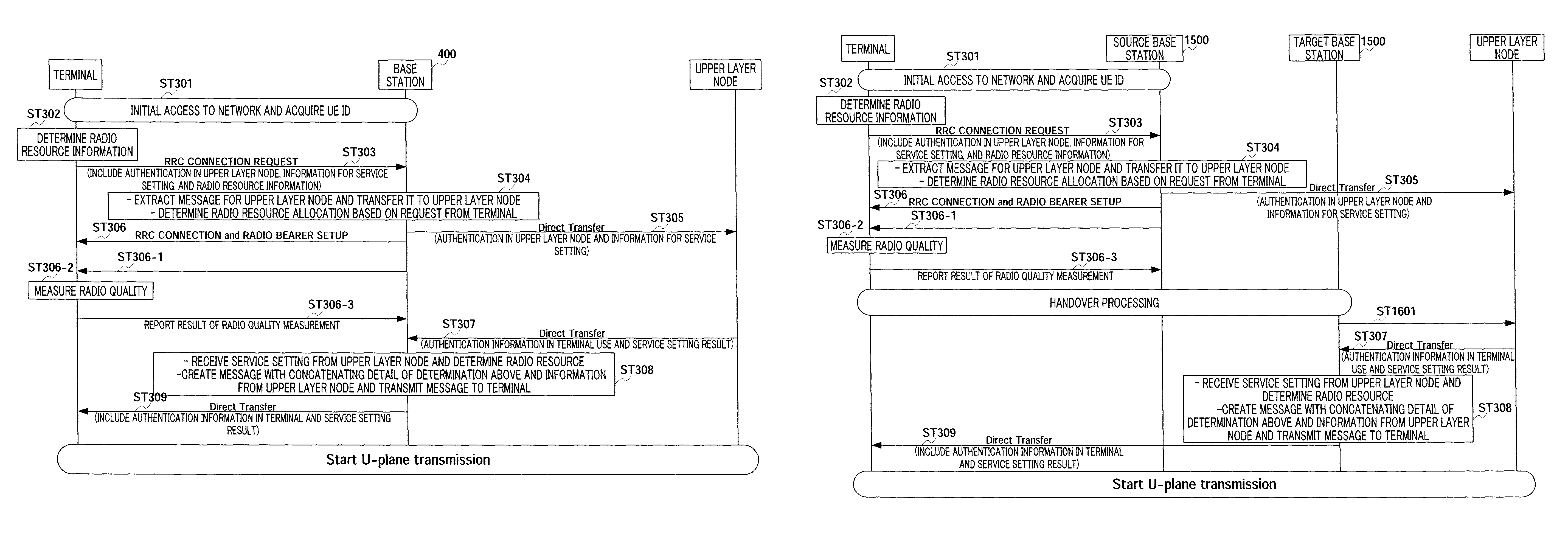
[0083]FIG. 7 is a block diagram showing the configuration of base station 400 according to Embodiment 2 of the present invention. Referring to this figure, radio quality measurement controlling section 401 stores cell information and so on, and, upon receiving an RRC connection establishment notice from radio control section 107, controls the terminal to measure radio quality. To be more specific, radio quality measurement controlling section 401 notifies to the terminal which cells are measured, how the cells are measured (for example, bands and cycles) and how to report. That is, radio quality measurement controlling section 401 transmits control information for controlling this terminal, to terminal control message transmitting section 105.

[0084]FIG. 8 is a sequence diagram showing the operations of the network according to Embodiment 2 of the present invention. Further, in FIG. 8, the same reference numerals are assigned to the same parts as in FIG. 5, and description thereof in...

embodiment 3

[0104]FIG. 17 is a block diagram showing the configuration of base station 600 according to Embodiment 3 of the present In this figure, providing service management section 601 manages the available services before the upper layer node issues an authentication and determines the details of services, and, when providing service management section 601 provides the managed service, providing service management section 601 outputs control information for providing services to terminal control message receiving section 101, terminal-originating upper layer node addressing message processing section 102, upper layer node control message receiving section 104, terminal control message transmitting section 105 and radio control section 107. These services include a SIP signaling message (hereinafter abbreviated as “SIP Signaling”), for example. That is, a SIP Signaling is a control operation before a terminal actually receives a service, and, after this processing, it is possible to provide...


PUM


Abstract

Disclosed are a base station device and a call connection method for reducing a call connection delay. According to the device and the method; in ST301, a terminal acquires an identifier managed in a base station (100); in ST302, radio resource information required for a service desired by the terminal is decided; in ST303, by using the identifier acquired in ST301, the terminal transmits a request for establishing RRC connection to the base station (100). In ST304, according to the radio resource information received from the terminal, the base station (100) decides the radio resource to be set for the terminal before authentication by an upper layer node, and the base station (100) extracts information destined to the upper layer node. In ST305, the information destined to the upper layer node is transmitted to the upper layer node. In ST306, the setting contents of the radio resource decided in ST304 are transmitted to the terminal.

Description

TECHNICAL FIELD[0001]The present invention relates to a radio communication base station apparatus and a call connection method.BACKGROUND ART[0002]One of the main targets of LTE (Long Term Evolution) and SAE (System Architecture Evolution) is to reduce call connection delay. A call connection includes two main components of RRC (Radio Resource Control) establishment and call control. For that reason, the point of call connection lies in how efficiently the operations of these two components are carried out. Here, RRC constitutes the core in radio control and has the functions of including mobility control of a terminal (e.g. a command to transfer a base station in connection). Moreover, a call connection is performed in an upper layer node and includes authentication and checking what call is established.[0003]FIG. 1 shows an overview of call connection steps in the conventional (UMTS) scheme. Referring to this figure, in step (hereinafter abbreviated as “ST”) 11, the terminal dete...

Claims


Application Information

Patent Timeline
Patent Type & Authority Patents(United States)
IPC IPC(8): H04M1/66H04W76/02H04W88/08
CPCH04W76/021H04W24/08H04W12/06H04W76/02H04W76/022H04W88/08H04W76/12H04W76/10H04W76/11H04W12/062
Inventor AOYAMA, TAKAHISAFUKUI, AKITO
Owner PANASONIC INTELLECTUAL PROPERTY CORP OF AMERICA
Why Eureka
Try Eureka