Triple band antenna

a triple band, antenna technology, applied in the field of triple band antennas, can solve the problem of inadequate dual-band antennas, and achieve the effect of increasing operating bandwidth and facilitating impedance matching

Active Publication Date: 2013-03-12
ASUSTEK COMPUTER INC
View PDF9 Cites 0 Cited by
  • Summary
  • Abstract
  • Description
  • Claims
  • Application Information

AI Technical Summary

Problems solved by technology

The dual-band antenna is inadequate due to the development of the WIMAX technology, which reflects the importance of the triple band antenna.

Method used


Image

  • Triple band antenna
  • Triple band antenna
  • Triple band antenna

Examples


Embodiment Construction

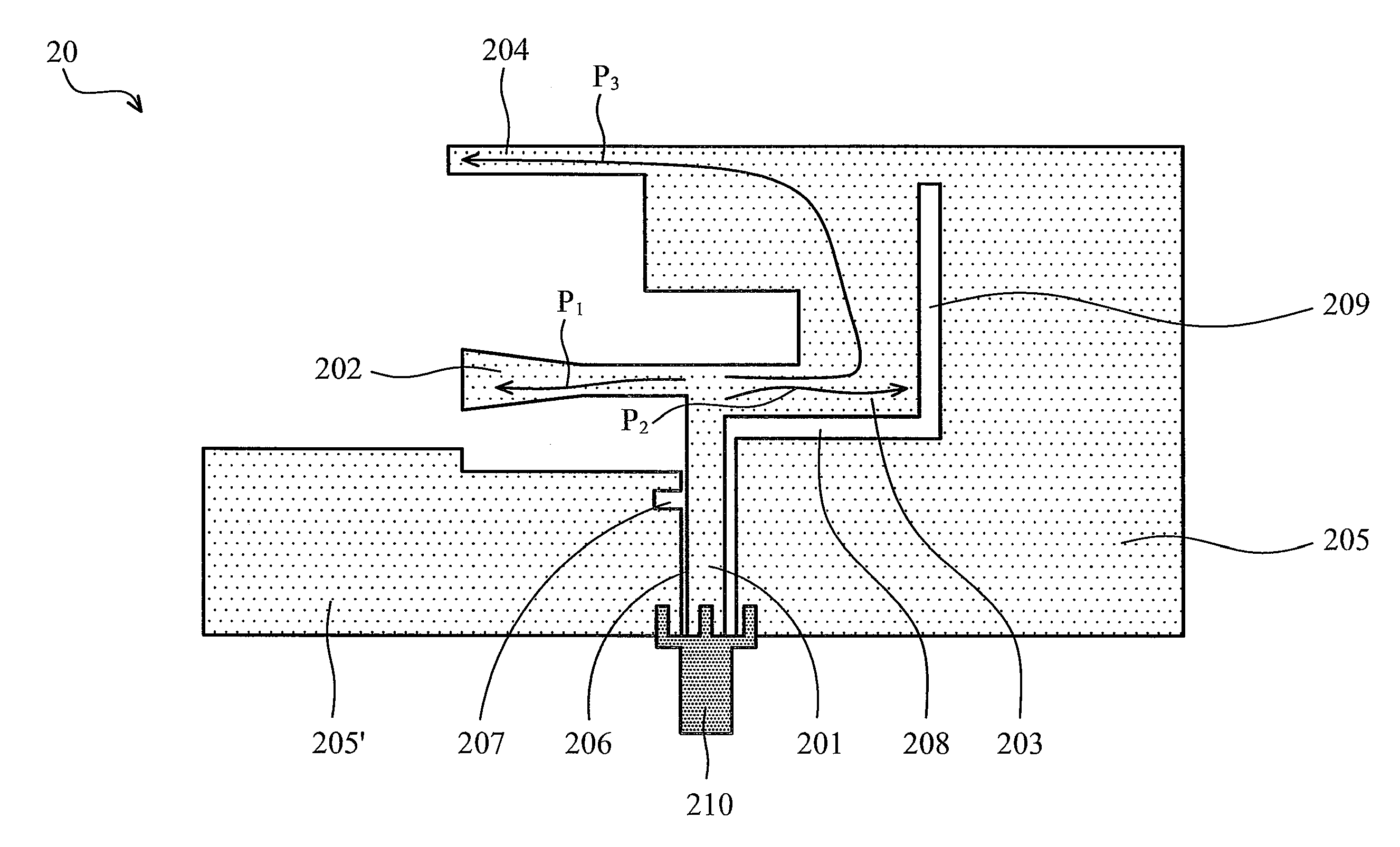
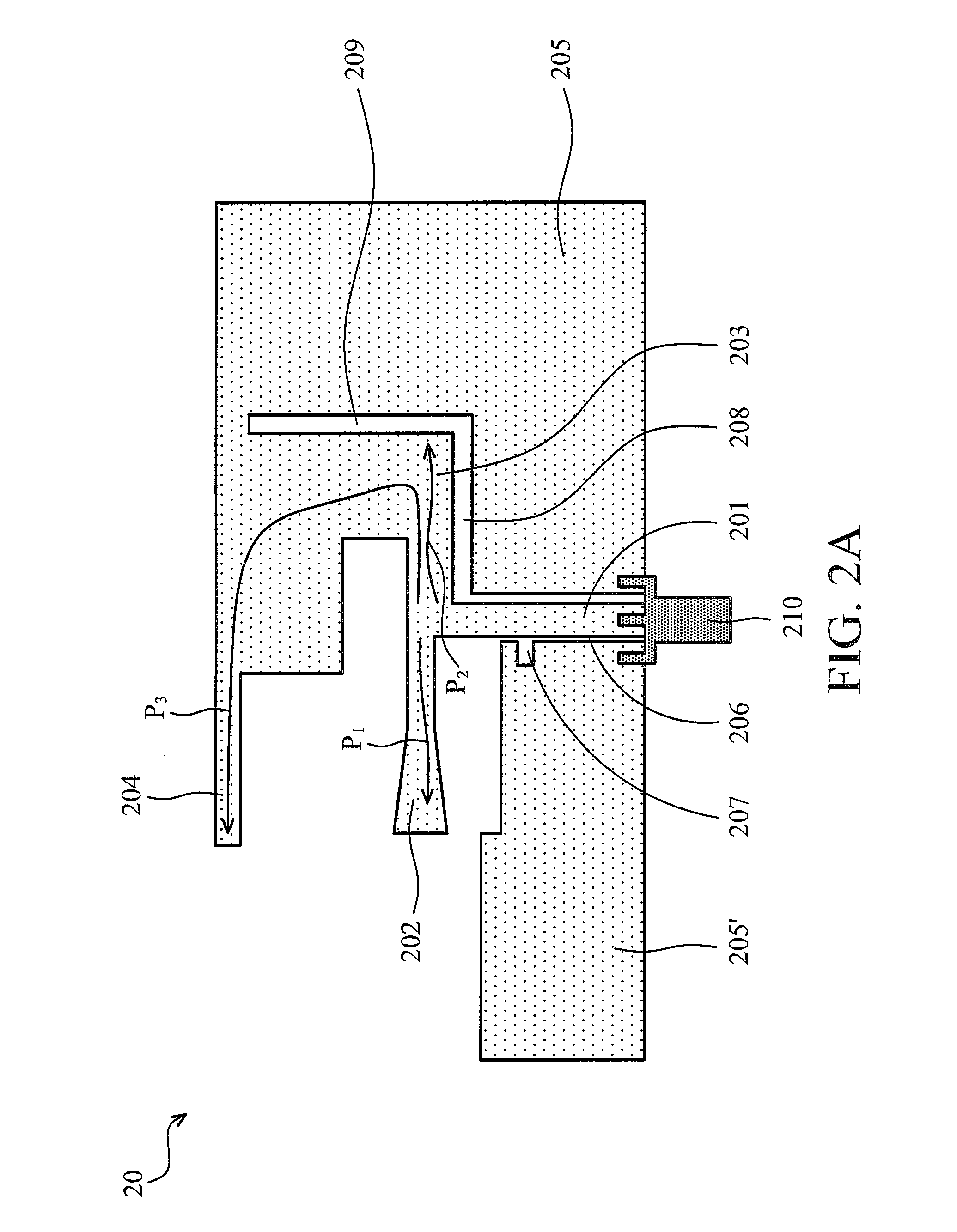
[0034]FIG. 2A is a schematic diagram showing a triple-band antenna according to the first embodiment of the invention, and FIG. 2B is a partial enlarged drawing of the first embodiment of the invention. As shown in FIG. 2A and FIG. 2B, a triple band antenna 20 includes a feed-in portion 201, a first radiating portion 202, a second radiating portion 203, a third radiating portion 204, two grounding portion 205, 205′, a first slit 206, a second slit 208 and a third slit 209. The triple band antenna 20 is a coplanar antenna, and its components are described as follows.

[0035]The first radiating portion 202 is connected to a first side 201a of a first end of the feed-in portion 201. A second end 203a of the second radiating portion 203 is connected to a second side 201b of the first end of the feed-in portion 201. The third radiating portion 204 is connected to a third end 203b of the second radiating portion 203. Therefore, the third radiating portion 204 and the second radiating portio...


PUM


Abstract

A triple band antenna includes a feed-in portion, a first radiating portion, a second radiating portion, a third radiating portion and a grounding portion. The first radiating portion is connected to a first side of a first end of the feed-in portion. A second end of the second radiating portion is connected to a second side of the first end of the feed-in portion. The third radiating portion is connected to a third end of the second radiating portion. The grounding portion is located at two sides of the feed-in portion.

Description

CROSS REFERENCE TO RELATED APPLICATIONS[0001]This application claims priority of Taiwan Patent Application No. 97102350, filed on Jan. 22, 2008, the entirety of which is incorporated by reference herein.BACKGROUND OF THE INVENTION[0002]1. Field of the Invention[0003]The invention relates to an antenna and, more particularly, to a triple band antenna.[0004]2. Description of the Related Art[0005]In recent years, wireless communication standards are closely integrated into mobile devices. For example, a mobile phone, a hand-held game, a MP3, a MP4, a PMP, a mobile TV, a GPS and a peripheral control device are integrated with a plurality of wireless standards such as the Wi-Fi standard, and they greatly need embedded antennas, and therefore, miniature antennas are essential components for embedded mobile applications.[0006]The design tendency is to be thin besides miniature. As for a 3C products on the market, such as a mobile phone, a common portable intelligent device and a consumer e...

Claims


Application Information

Patent Timeline
Patent Type & Authority Patents(United States)
IPC IPC(8): H01Q1/38H01Q5/00H01Q5/371
CPCH01Q1/38H01Q5/00H01Q5/371H01Q9/40H01Q9/0421
Inventor LIU, MING-YEN
Owner ASUSTEK COMPUTER INC
Why Eureka
Try Eureka