Slim triple band antenna array for cellular base stations

a technology of cellular base stations and antenna arrays, applied in the direction of polarised antenna unit combinations, individually energised antenna arrays, resonant antennas, etc., can solve the problems of reducing the number of antenna arrays in the base station to just three, affecting the environmental and visual impact of the network, and reducing the width of the base station antenna

Active Publication Date: 2013-07-30
COMMSCOPE TECH LLC
View PDF113 Cites 19 Cited by
  • Summary
  • Abstract
  • Description
  • Claims
  • Application Information

AI Technical Summary

Benefits of technology

[0014]The above mentioned drawbacks are overcome with a triple-band antenna array as of claim 1, or of claim 74, or of claim 75, with a slim triple-band base station as of claim 68, with a radiating element as of claim 48, with a method to couple capacitively an electrical signal to a radiating element as of claim 39, and with the method to reduce the environmental and visual impact of a network of cellular or wireless base stations as of claim 76. Further embodiments are disclosed in the dependent claims.
[0015]The invention provides devices and means to minimize the visual impact and cost of mobile telecommunication networks while at the same time simplifying the logistics of the deployment, installation and maintenance of such networks. The invention provides a slim triple-band base station, which integrates multiple mobile / cellular services into a compact radiating system (or radiating part). Such a base station could advantageously integrate the 1st, 2nd, and 3rd generation of mobile and wireless communications services, increasing the number of cellular users that can communicate with a given base station, and hence increasing the capability of the network for a given (i.e., fixed) network of base stations, or alternatively reducing the number of base stations required in the network for a fixed capacity. The radiating system optionally includes an adjustable electrical tilt mechanism for one or more of the operating frequency bands, thus providing additional flexibility when planning, adjusting, and optimizing the coverage, and increasing the capacity of the network. Also, the slim form factor of the radiating system as described by the present invention enables slimmer (i.e., smaller diameter) and lighter-weight towers to support such radiating systems, which are easier to carry, for example, to the roof of a building (for instance through elevators, through staircases or with small lift systems) where the radiating systems might be installed.

Problems solved by technology

The use of multiple single-band antenna arrays (or a combination of single-band and dual-band antenna arrays) in a triple-band base station will typically lead to bulky and mechanically complex structures, hardly disguisable with the surrounding environment.
Furthermore, a large antenna array count will likely result in a costly solution.
Although, this approach reduces the number of antenna arrays in the base station to just three (i.e., one per sector), it still performs poorly in terms of minimizing the visual impact of the base station, as the dimensions of these antenna arrays, specially their width, are significantly larger than the dimensions of a single-band antenna array.
As governments and public administrations endeavor in minimizing the visual impact of the base station of cellular communications networks, it is becoming more and more difficult for network operators and mobile service providers to acquire new sites and / or obtain the license to set up new base stations in cities and villages around the world.
The visual impact due to the size and number of antenna arrays in a base station has been a rising issue for network operators and consumers, creating the demand for smaller-sized antenna arrays for base stations, with which to reduce substantially the visual impact of the base station but without compromising the level of performance and functionality of current solutions.

Method used


Image

  • Slim triple band antenna array for cellular base stations
  • Slim triple band antenna array for cellular base stations
  • Slim triple band antenna array for cellular base stations

Examples


Embodiment Construction

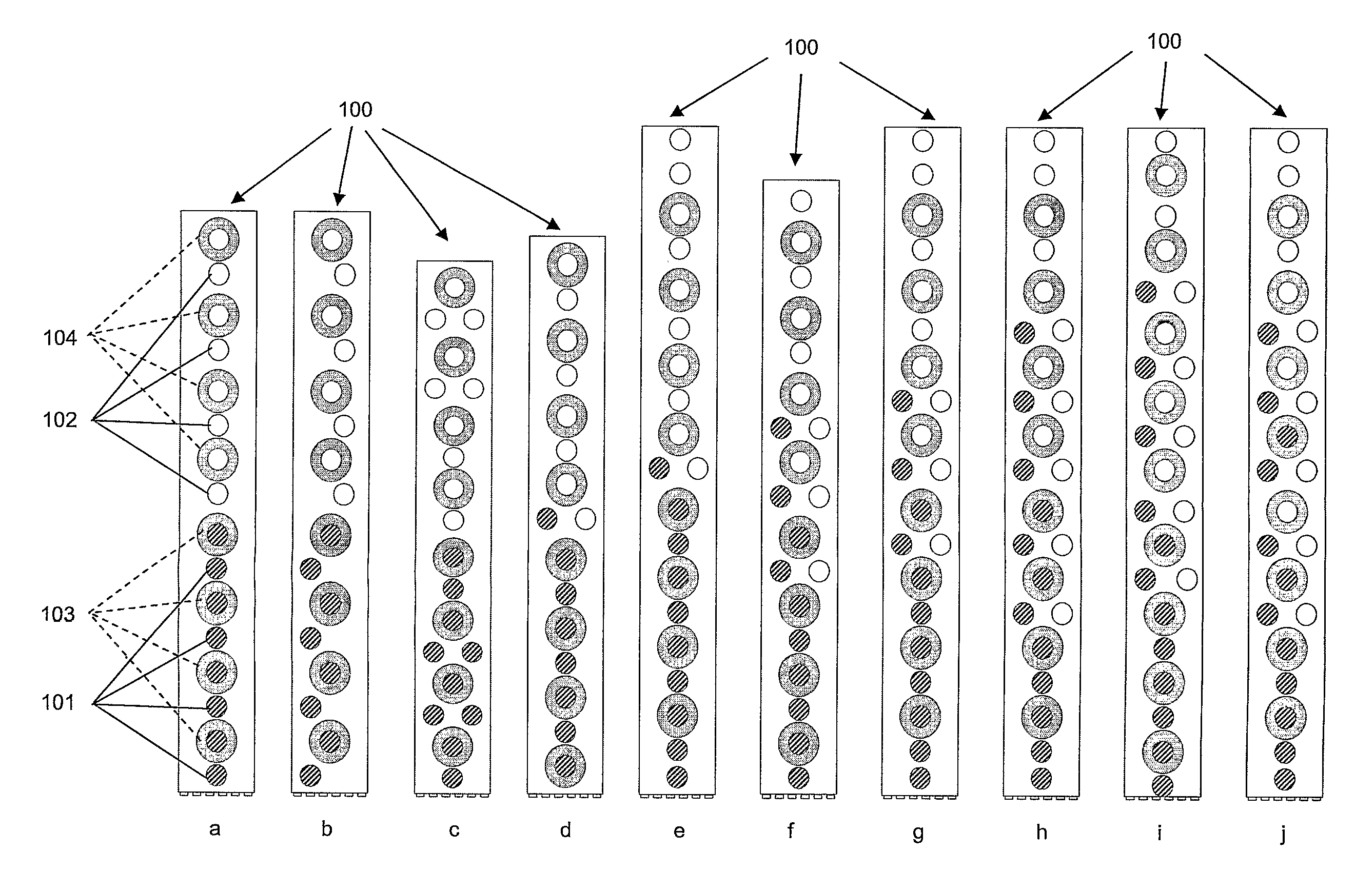
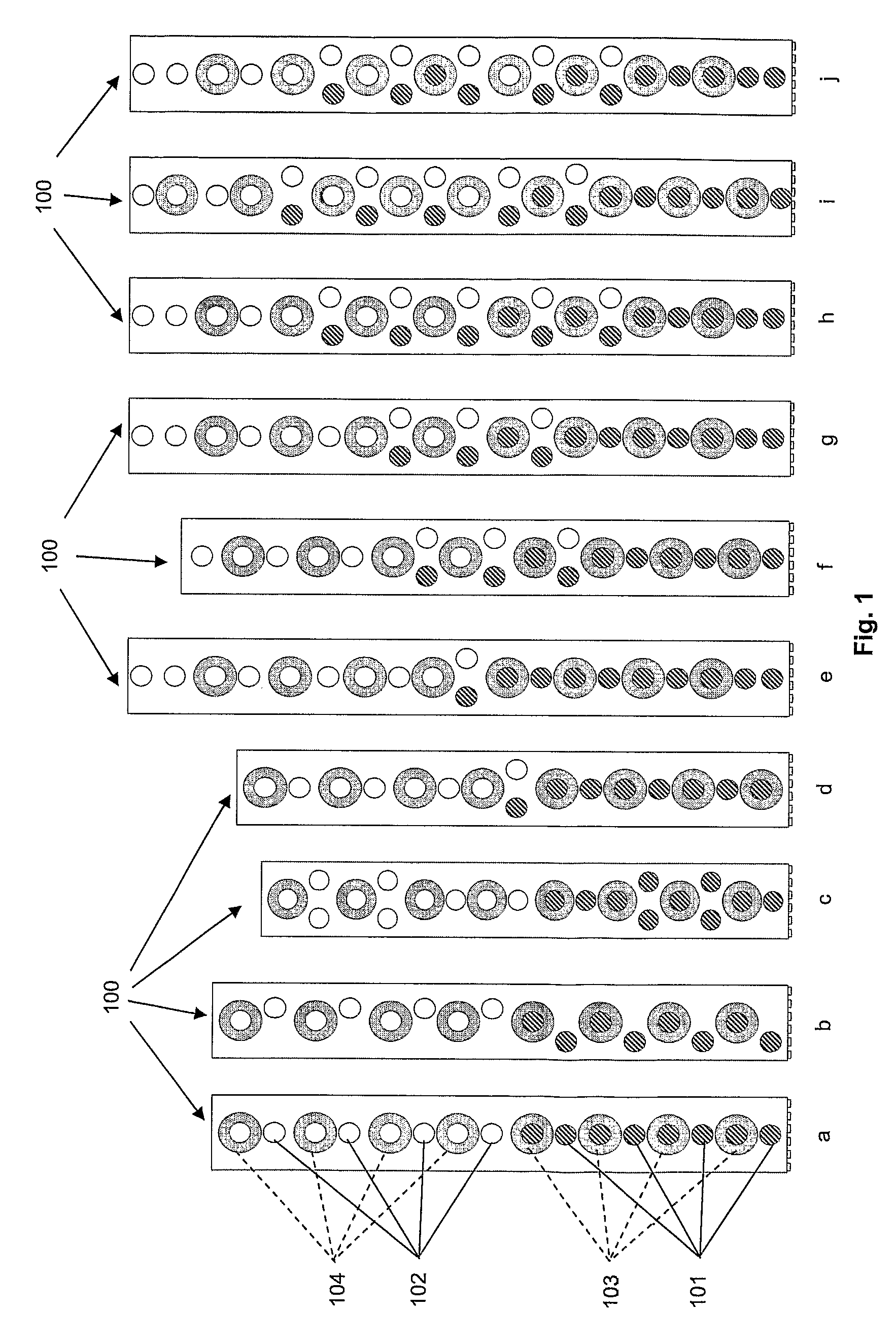
[0115]FIG. 1 presents, without any limiting purpose, several ways in which the radiating elements of a triple-band antenna array can be arranged according to the present invention. In order to further reduce the size of the triple-band antenna array (100), its radiating elements may be interlaced. In FIG. 1, the circles of different sizes and / or shading indicate the position in the array of the radiating elements belonging to the different sets (101, 102, 103, 104). The radiating elements are depicted as circles for illustration purposes only, and they do not necessarily represent their actual shape. In FIG. 1a, the combination of a first set of radiating elements (101) with the third set of radiating elements (103) provides a first frequency band of the antenna array (100). Then, the combination of a second set of radiating elements (102) with the fourth set of radiating elements (104) provides a second frequency band of the antenna array (100). Finally, the combination of the thir...


PUM


Abstract

The present invention refers to a triple-band antenna array for cellular base stations operating at a first frequency band and at a second frequency band within a first frequency range, and also at a third frequency band within a second frequency range. Said triple-band antenna array comprises a first set of radiating elements operating at the first frequency band, a second set of radiating elements operating at the second frequency band, a third set of radiating elements operating at both the third and the first frequency bands, and a fourth set of radiating elements operating at both the third and the second frequency bands. The radiating elements are arranged in such a way that at least some of the radiating elements of the first set are interlaced with at least some of the radiating elements of the third set, and at least some of the radiating elements of the second set are interlaced with at least some of the radiating elements of said fourth set. Further the invention relates to a slim triple-band base station for mobile / cellular services that includes in its radiating part two or more of said triple-band antenna arrays.

Description

CROSS-REFERENCE TO RELATED APPLICATIONS[0001]This patent application is a national stage filing of International Patent Application No. PCT / IB2006 / 002975, which was filed on Oct. 12, 2006. International Patent Application No. PCT / IB2006 / 002975 claims priority from European Application No. EP 05109585.9, which was filed on Oct. 14, 2005. International Patent Application No. PCT / IB2006 / 002975 claims priority from U.S. Provisional Patent Application No. 60 / 727,981, which was filed on Oct. 18, 2005. International Patent Application No. PCT / IB2006 / 002975, European Application No. EP 05109585.9, and U.S. Provisional Patent Application No. 60 / 727,981 are incorporated herein by reference.[0002]The present invention relates to an antenna array for cellular base stations, in particular to a slim triple-band antenna array.OBJECT OF THE INVENTION[0003]The present invention refers to a slim triple-band antenna array for cellular base stations, which provides a reduced width of the base station a...

Claims


Application Information

Patent Timeline
Patent Type & Authority Patents(United States)
IPC IPC(8): H01Q21/00H01Q5/42
CPCH01Q1/42H01Q21/065H01Q21/30H01Q5/50H01Q5/307H01Q5/42H01Q5/0027H01Q9/0414H01Q9/0435H01Q9/0457H01Q21/08H01Q1/246H01Q1/48
Inventor PUENTE, CARLESBORJA, CARMENTEILLET, ANTHONYKIRCHOFFER, DILLONANGUERA, JAUME
Owner COMMSCOPE TECH LLC
Why Eureka
Try Eureka