Position detection apparatus

a technology of position detection and pointing performance, which is applied in the direction of mechanical pattern conversion, instruments, computing, etc., can solve the problems of capacitive type system deterioration of position detection performance, and achieve the effects of preventing deterioration of detection performance, increasing spatial distance, and stabilizing position pointing performan

Active Publication Date: 2013-03-12
WACOM CO LTD
View PDF10 Cites 5 Cited by
  • Summary
  • Abstract
  • Description
  • Claims
  • Application Information

AI Technical Summary

Benefits of technology

[0008]The present invention has been made in view of such a point as described above, and according to one aspect of the present invention a position detection apparatus incorporating a plurality of position detection systems is provided, wherein interference of transmission signals when these position detection systems operate at the same time can be suppressed thereby to prevent deterioration of a detection performance of the position pointed to by a pointer such as a pen or a finger to achieve a stabilized position pointing performance.
[0009]In order to solve the problem described above, according to a position detection apparatus of the present invention, selection position information of a transmission conductor in a first position detection system is utilized for selecting a reception conductor in a second position detection system thereby to increase the spatial distance between the transmission conductor in the first position detection system and the reception conductor in the second position detection system as much as possible. Alternatively, it is also possible to carry out selection control of a transmission conductor based on the selection position information of a reception conductor. Further, a relationship of frequency interleave is provided between a transmission signal to be supplied to the transmission conductor in the first position detection system and another transmission signal to be supplied to the transmission conductor in the second position detection system.
[0010]According to the present invention, in the position detection apparatus wherein a plurality of position detection systems are combined and operated simultaneously with each other, such a situation that a transmission signal to a sensor conductor used by one of the position detection apparatus is received as noise by the other position detection apparatus to have a negative influence can be suppressed effectively. Consequently, the position detection apparatus can be provided which prevents deterioration of the position detection performance and can achieve a stabilized position detection function.

Problems solved by technology

This alternating magnetic field sometimes has an influence as noise on the position detection section of the capacitive type system and sometimes gives rise to deterioration of the position detection performance by the capacitive type system.

Method used


Image

  • Position detection apparatus
  • Position detection apparatus
  • Position detection apparatus

Examples


first embodiment

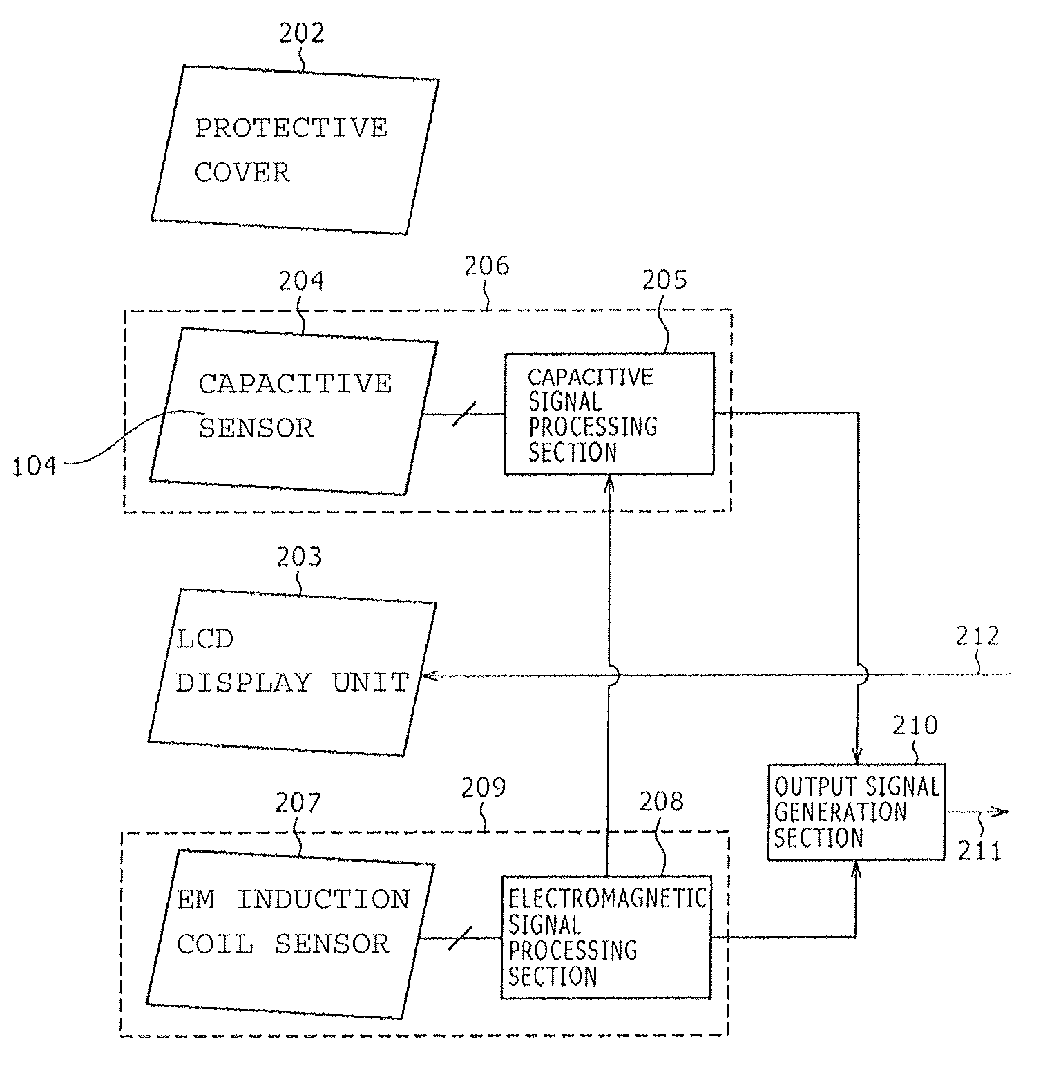
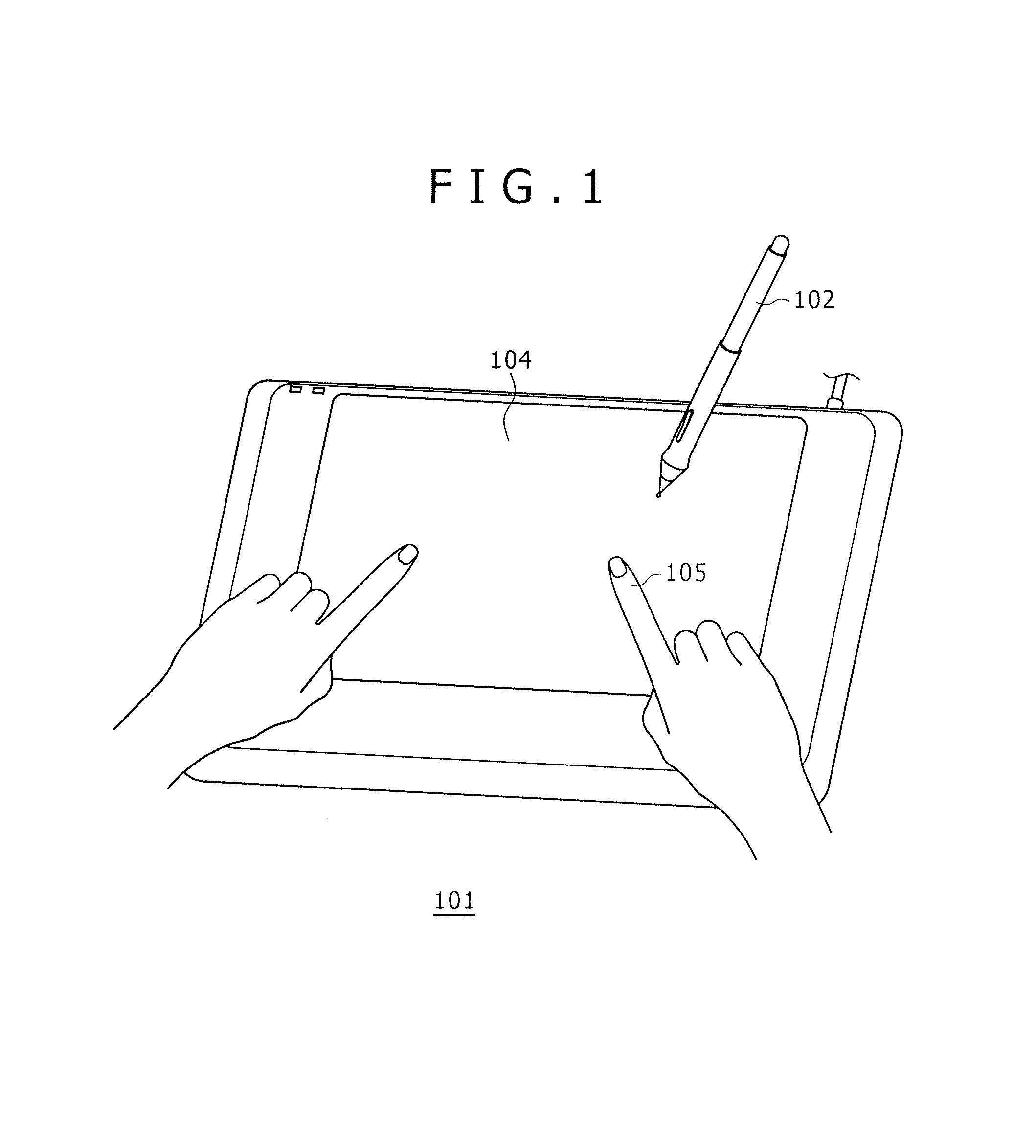
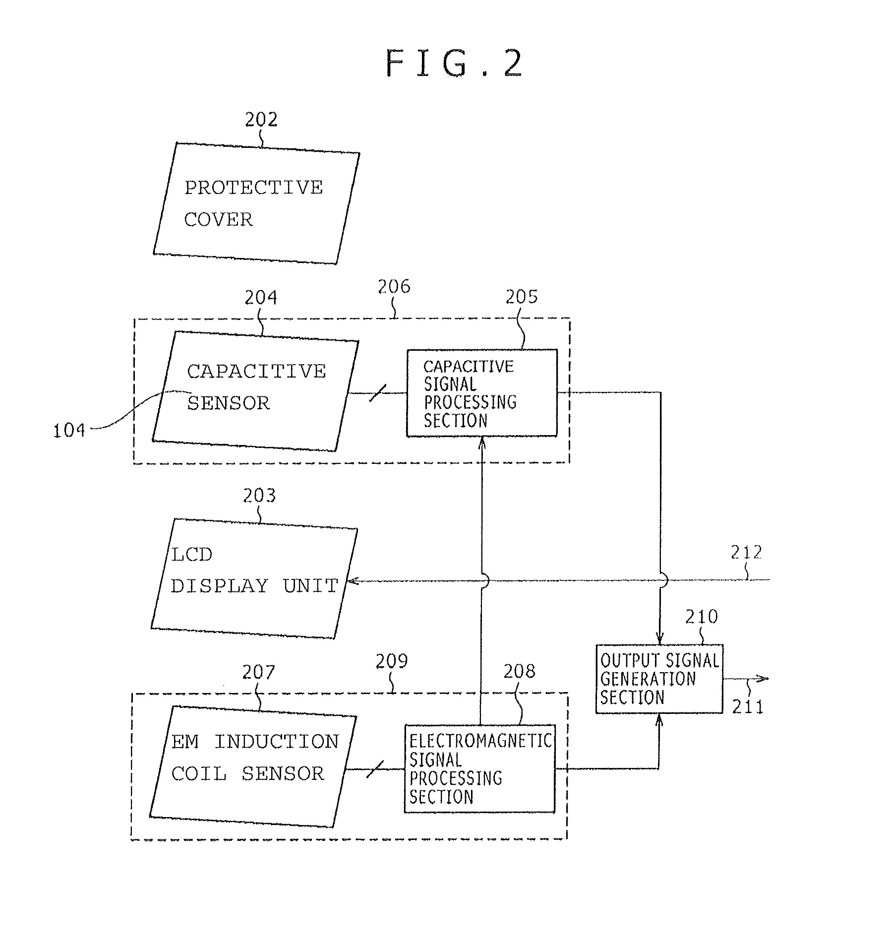
[0020]FIG. 1 is a perspective view of an entire position detection apparatus showing an example of a first embodiment of the present invention. The position detection apparatus 101 includes a position detection region 104 for detecting the positions pointed to by a pen 102 as a first position pointer and a finger 105 as a second position pointer, and position information corresponding to an operation of the pen 102 and the finger 105 is supplied to an apparatus such as a personal computer (not shown). Further, a transparent protective cover of a glass plate, an acrylic resin plate or the like, hereinafter described, is disposed on the position detection region 104, and a display section such as a known LCD display unit is disposed below the protective cover. The LCD display unit displays a signal supplied thereto from the apparatus such as a personal computer.

[0021]Accordingly, by operating the pen 102 on the position detection region 104, a user can draw on the LCD display unit. Si...

second embodiment

Frequency Interleave

[0048]FIG. 7A illustrates a signal supplied to the loop coils 408 provided in the electromagnetic type position detection section 209 (referred to as “EMR (Electro-Magnetic Resonance) driving signal”) and FIG. 7B illustrates a signal supplied to the transmission conductors 504 provided in the capacitive type position detection section 206 (referred to as capacitive driving signal).

[0049]In FIG. 7A, the oscillation circuit 402 shown in FIG. 4 generates a sine wave AC signal of a frequency (e.g., 500 KHz) substantially equal to the resonance frequency of the resonance circuit of the pen 102. In the present embodiment, the loop coils 408 include four loop coils 408a, 408b, 408c and 408d for the convenience of description, and each of the coils is placed into a selected state for a period of 64 μS by the coil selection circuit 407, which is controlled by a predetermined sequence in accordance with an instruction from the first control section 409. Further, the select...


PUM


Abstract

A position detection apparatus is provided, which includes a plurality of position detection systems such as an electromagnetic-type position detection system and a capacitive-type position detection system. The apparatus is configured to select a transmission conductor among a plurality of transmission conductors in a first position detection system, and to select a reception conductor among a plurality of reception conductors in a second position detection system, so as to increase the spatial distance between the selected transmission conductor in the first position detection system and the selected reception conductor in the second position detection system as much as possible, to thereby reduce interference. Further, a relationship of frequency interleave may be provided between a transmission signal to be supplied to the transmission conductor in the first position detection system and another transmission signal to be supplied to the transmission conductor in the second position detection system.

Description

CROSS REFERENCE TO RELATED APPLICATIONS[0001]The present application claims the benefit under 35 U.S.C. 119 of Japanese Patent Application No. 2010-049743, filed Mar. 5, 2010, the entire content of which is being incorporated herein by reference.TECHNICAL FIELD[0002]This invention relates to a technique suitable for application to a position detection apparatus wherein a plurality of position detection systems are combined. More particularly, the present invention relates to a position detection apparatus wherein a position detection system of an electromagnetic type for detecting a position pointed to, for example, by a position pointing device (pen) as a pointer is combined with a position detection system of a capacitive type for detecting a position pointed to, for example, by a finger as a pointer.BACKGROUND[0003]A touch panel apparatus is available wherein a position detection apparatus for detecting a pointed position by a pointer is combined with a display area of a liquid c...

Claims


Application Information

Patent Timeline
Patent Type & Authority Patents(United States)
IPC IPC(8): G06F3/045G06F3/046G06F3/044G06F3/033G06F3/041
CPCG06F3/044G06F3/046G06F2203/04106G06F3/0446G06F3/03
Inventor ODA, YASUOSUGIYAMA, YOSHIHISA
Owner WACOM CO LTD
Why Eureka
Try Eureka