
Refrigerator

a technology for refrigerators and freezers, which is applied in the field of refrigerators, can solve the problems of increasing inconvenient user's ice removal, and difficulty for a short man or a child to take ice out of refrigerators, so as to reduce the manufacturing cost of refrigerators and maximize the inner space of refrigerators. the effect of the freedom of design of the refrigerator

Active Publication Date: 2013-03-19
LG ELECTRONICS INC
View PDF17 Cites 2 Cited by
  • Summary
  • Abstract
  • Description
  • Claims
  • Application Information

AI Technical Summary

Benefits of technology

[0047]The refrigerator according to the present invention has various effects as follows.
[0048]First, since the refrigerator according to the present invention includes the cold air guiding device for guiding the cold air generated by the heat exchanger, which controls the temperature of the freezing compartment, to the ice malting compartment, it is possible to appropriately select the position of the ice making compartment irrespective of the structure or capacity of the refrigerator. Accordingly, it is possible to achieve an improvement in the freedom of design of the refrigerator, and a reduction in the manufacturing costs of the refrigerator, and to maximize the inner space of the refrigerating compartment.
[0049]Second, in the refrigerator according to the present invention, it is possible to conveniently use the refrigerating compartment, and to easily take ice out of the ice making compartment because the freezing compartment is arranged beneath the refrigerating compartment.
[0050]Third, in the refrigerator according to the present invention, it is possible to prevent a frosting phenomenon from occurring in the refrigerating compartment due to the cold air guiding device, which guides cold air, because the heater is arranged on the inner surface of the refrigerating compartment.
[0051]Fourth, in the refrigerator according to the present invention, it is possible to easily fill a foaming liquid because the duct is arranged at a correct position between the outer wall and inner wall, which form one side wall of the refrigerating compartment, by spacing ribs and / or spacing protrusions.
[0052]Fifth, since the refrigerator according to the present invention includes the duct holder for fixing the duct to one side wall of the refrigerating compartment, it is possible to easily install the duct.

Problems solved by technology

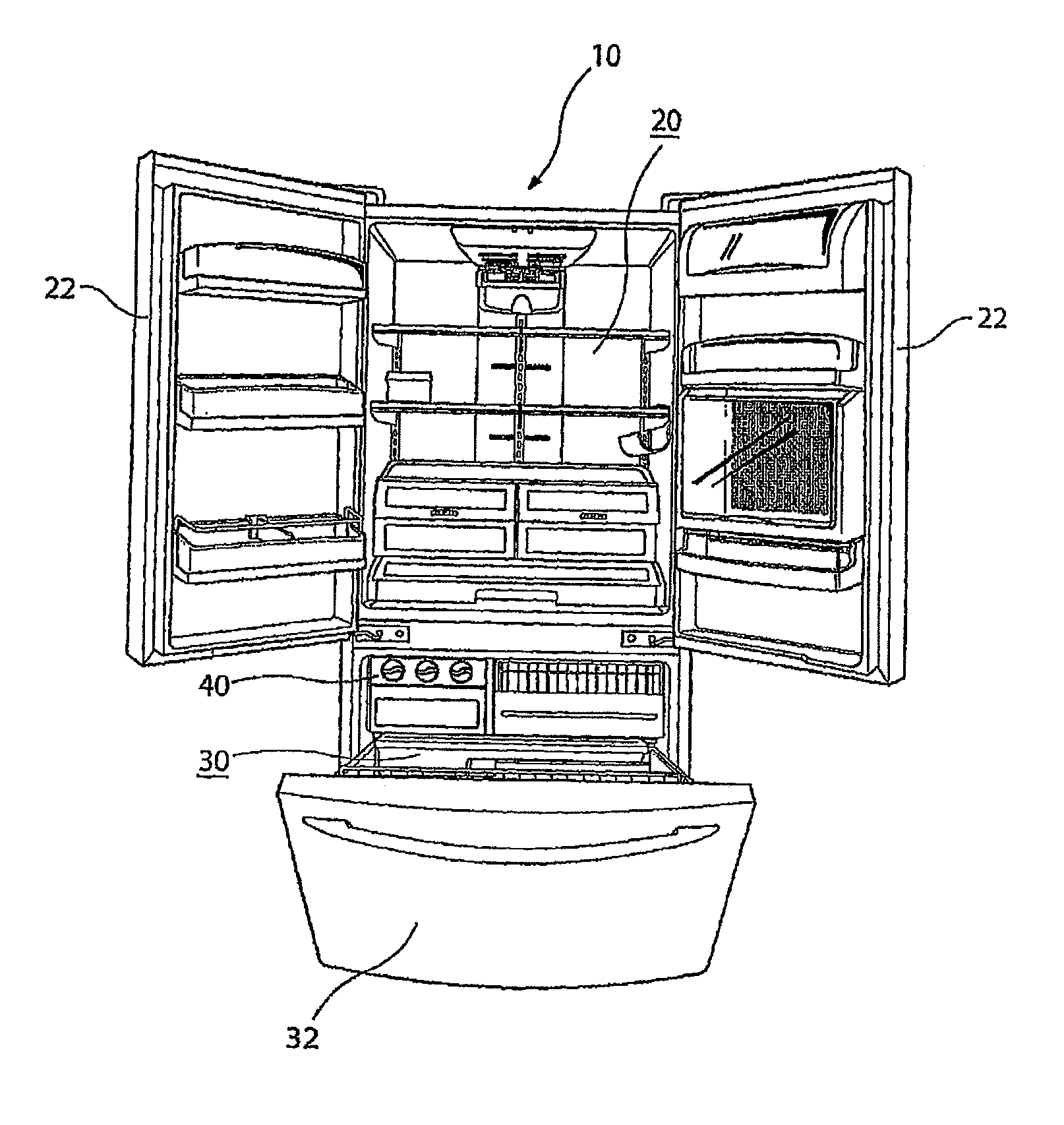
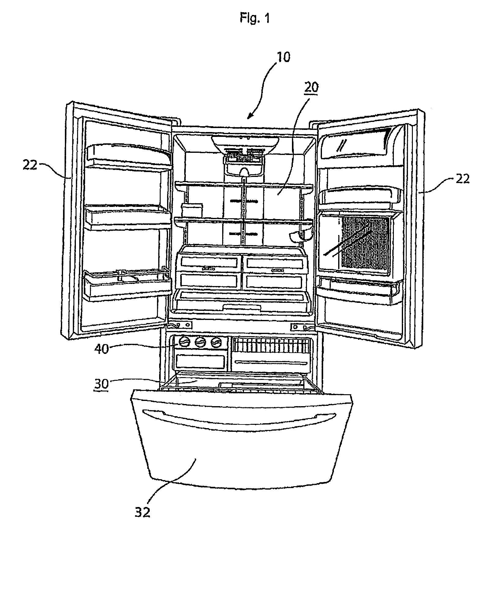
First, there is a problem in that the ice maker 40, which makes ice, is arranged in the interior of the freezing compartment 30, and the freezing compartment 30 is arranged beneath the refrigerating compartment 20 in the conventional refrigerator having the above-mentioned configuration. That is, it is inconvenient for the user to take ice out of the ice maker 40 because the user must operate the ice maker 40 after opening the freezing compartment door 32 while bending his body.
In this case, however, it is difficult for a short man or a child to take ice out of the ice maker 40 arranged in the interior of the freezing compartment 30, after opening the freezing compartment 30, in the case in which the refrigerator has a large size.
In this case, however, there are various problems, for example, an increase in the manufacturing costs of the refrigerator, an increase in the volume of the refrigerator, and a difficulty in the manufacture of the refrigerator, because an ice-making heat exchanger must be installed in the ice making compartment.

Method used


Image

  • Refrigerator
  • Refrigerator
  • Refrigerator

Examples


first embodiment

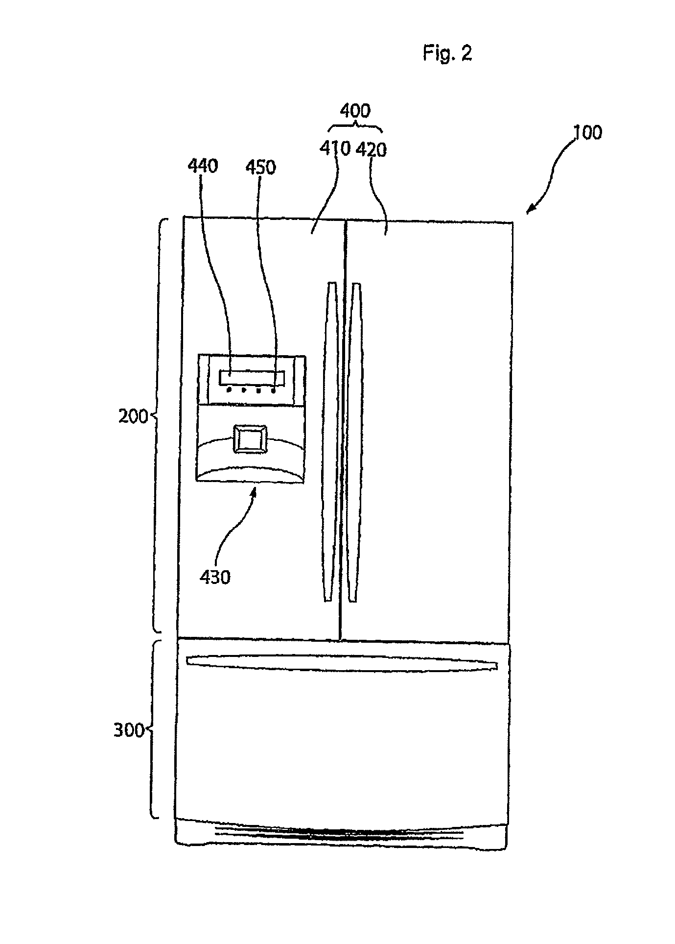
[0079]FIG. 2 is a front view illustrating a refrigerator according to the present invention. FIG. 3 is a perspective view illustrating an opened state of refrigerating compartment doors and an opened state of a freezing compartment door in the refrigerator shown in FIG. 2. FIG. 4 is a perspective view illustrating flow paths of cold air in an ice making compartment and a cold air guide device in the refrigerator shown in FIG. 2. FIG. 5 is a perspective view illustrating the inner side of a part of one refrigerating compartment door where the ice making compartment is arranged, in the refrigerator shown in FIG. 2.

[0080]Referring to FIGS. 2 to 5, the refrigerator according to the first embodiment of the present invention includes a refrigerator body 100, and an ice making compartment 500 in which ice is made.

[0081]The inner space of the refrigerator body 100 is partitioned into a refrigerating compartment 200 and a freezing compartment 300.

[0082]Although not shown, shelves and drawers...

second embodiment

[0154]Hereinafter, a refrigerator according to the present invention will be described with reference to FIGS. 6 to 9.

[0155]FIG. 6 is a perspective view of the refrigerator according to the second embodiment of the present invention, illustrating an opened state of refrigerating compartment doors and an opened state of a freezing compartment door. FIG. 7 is a perspective view illustrating a cold air guide device and one door of the refrigerator according to the second embodiment of the present invention. FIG. 8 is an exploded perspective view illustrating a sealing unit applied to the refrigerator shown in FIG. 7. FIG. 9 is a sectional view illustrating the sealing unit applied to the refrigerator shown in FIG. 7.

[0156]The basic constituent elements of the refrigerator according to the second embodiment of the present invention are identical to those of the refrigerator according to the first embodiment of the present invention. In the following description given in conjunction with...

third embodiment

[0196]Hereinafter, a refrigerator according to the present invention will be described with reference to FIGS. 10 and 11.

[0197]FIG. 10 is a front view illustrating an inner case included in a refrigerator door which is applied to the refrigerator according to the third embodiment of the present invention. FIG. 11 is an exploded perspective view illustrating a door duct unit provided at the inner case shown in FIG. 10, and a sealing unit provided at the door duct unit.

[0198]The basic constituent elements of the refrigerator according to the third embodiment of the present invention are identical to those of the refrigerator according to the first embodiment and / or second embodiment of the present invention. In the following description given in conjunction with the refrigerator according to the third embodiment of the present invention, the constituent elements identical to those of the first embodiment and / or second embodiment of the present invention will be designated by the same ...


PUM


Abstract

A refrigerator is disclosed which enables the user to easily take ice out of an ice maker without causing a variation in the capacity of the refrigerator or a limitation on the position of a freezing compartment. The refrigerator includes a refrigerator body which includes a freezing compartment and a refrigerating compartment, an ice making compartment which is arranged in the refrigerating compartment, to make ice, a heat exchanger which generates cold air for freezing food stored in the freezing compartment, and a cold air guiding device which guides the cold air generated by the heat exchanger to the ice making compartment, to enable the ice making compartment to make ice.

Description

[0001]This application is a Continuation of application Ser. No. 11 / 815,192, filed on May 19, 2008, now abandoned, and for which priority is claimed under 35 U.S.C. §120. Application Ser. No. 11 / 815,192 is a National Stage Entry of PCT International Application No. PCT / KR2006 / 000357, filed on Feb. 1, 2006, which designates the United States, and for which priority is claimed under 35 U.S.C. §120. This application also claims priority under 35 U.S.C. §119(a) on Patent Application No. 10-2005-0008905, filed in the Republic of Korea on Feb. 1, 2005, Patent Application No. 10-2005-0009362, filed in Korea on Feb. 2, 2005, Patent Application No. 10-2005-0012991, filed in the Republic of Korea on Feb. 17, 2005, Patent Application No. 10-2005-0014749, filed in the Republic of Korea on Feb. 23, 2005, Patent Application No. 10-2005-0015693, filed in the Republic of Korea on Feb. 25, 2005, Patent Application No. 10-2005-0015692, filed in the Republic of Korea on Feb. 25, 2005, Patent Applicati...

Claims


Application Information

Patent Timeline
Patent Type & Authority Patents(United States)
IPC IPC(8): F25D3/02
CPCF25D17/065F25D23/04F25C5/005F25D2400/06F25D17/045F25D21/04F25D23/087F25D2317/062F25D2317/0664F25D2317/067F25D2317/0671F25D2317/0672F25D2323/021F25D2400/04F25C2400/10F25C5/22
Inventor LEE, BOK DONGLEE, SEUNG-MOKHAN, KAP ROKYANG, CHANG WOAN
Owner LG ELECTRONICS INC
Learn More