Supercharge Your Innovation With Domain-Expert AI Agents!

Appliance pump

a technology for applications and pumps, applied in the field of pumps, can solve the problems of affecting the efficiency of the pump, causing the impeller chamber to be filled with air, and causing the air to remain trapped in the impeller chamber

Active Publication Date: 2013-03-19
FISHER & PAYKEL APPLIANCES LTD
View PDF12 Cites 3 Cited by
  • Summary
  • Abstract
  • Description
  • Claims
  • Application Information

AI Technical Summary

Benefits of technology

The present invention is a pump for a washing appliance that improves on previous pumps. It includes a pump casing with a cylindrical side wall, a bottom wall, and a ceiling. The pump has an inlet and an outlet, with an inlet conduit that extends from the pump casing at a small angle above the horizontal. The ceiling has a downwardly extending dividing wall section with an inlet side and an outlet side. The upper most periphery of the inlet is above or flush with the inlet side of the dividing wall. The impeller in the pump has vanes that rotate across the dividing wall section. The pump casing is fixed to the floor of the wash chamber and the inlet and outlet are located side-by-side in the side to wall. The invention also includes a washing appliance with a sump and a pump.

Problems solved by technology

However, the pump design does not allow all trapped air to be bled off, such that a level of air can remain trapped in the impeller chamber.
While this drain pump operates satisfactorily, the efficiency of the pump can be affected by the level of air that can remain trapped.

Method used


Image

  • Appliance pump
  • Appliance pump
  • Appliance pump

Examples


Embodiment Construction

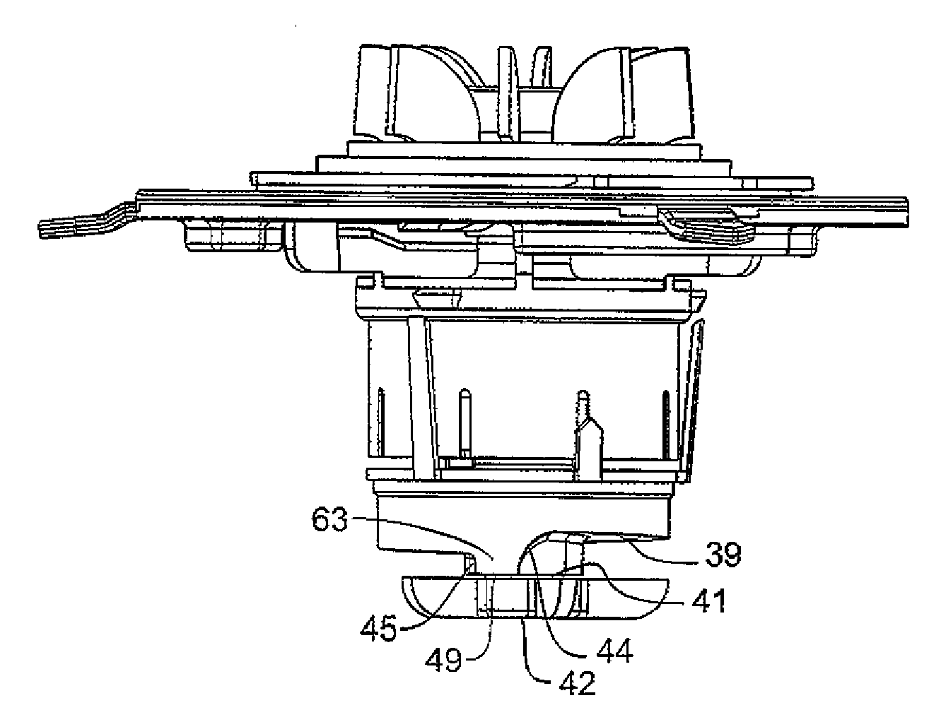
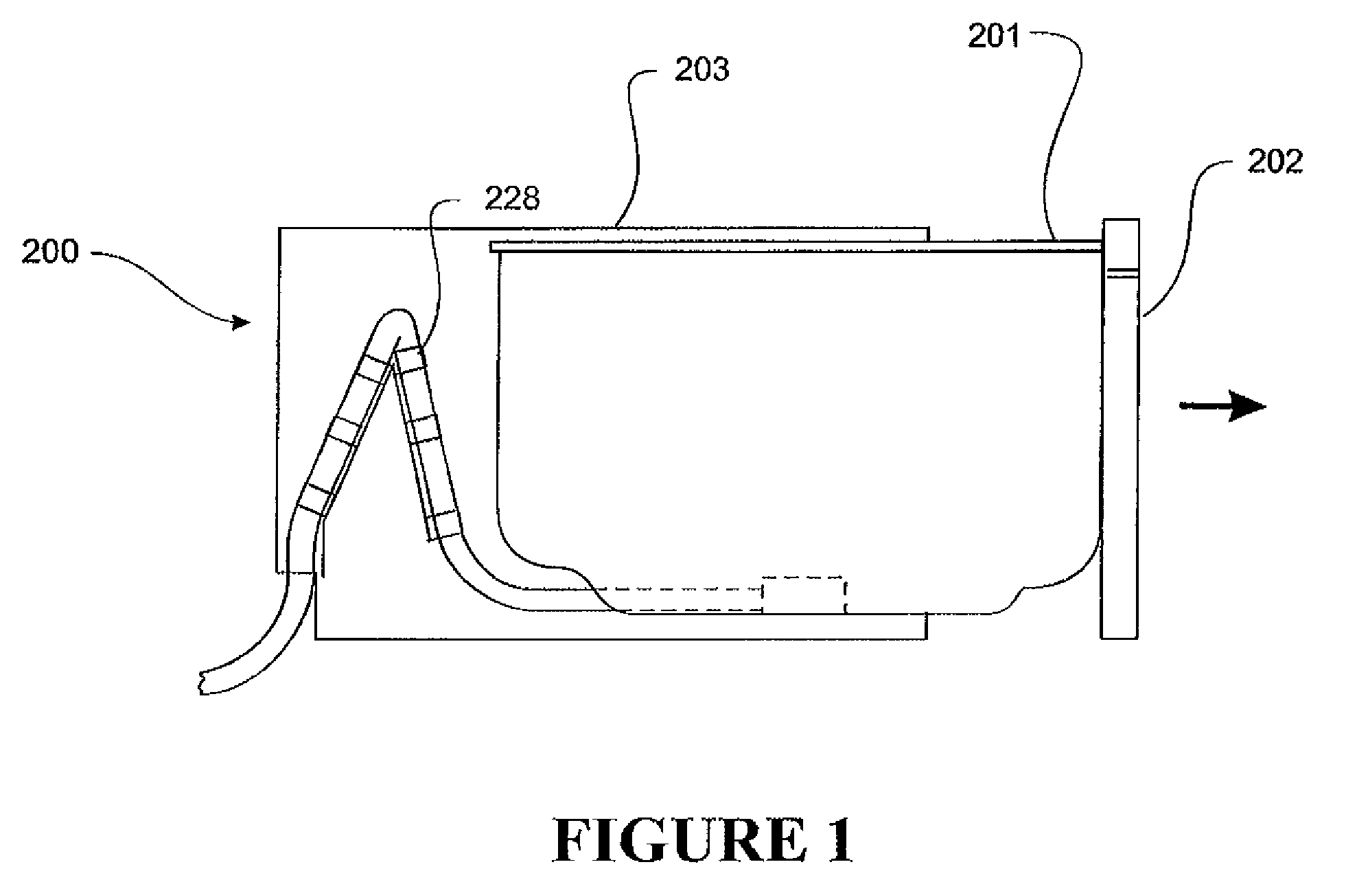
[0046]The washing appliance 200 incorporating the pump of the present invention is of the type illustrated in FIG. 1. A wash chamber 201 (with all wash system components) fitted with a front panel 202 is slidably mounted within a cabinet 203 in a ‘drawer’ arrangement. The wash chamber has an open top and is withdrawn from the cabinet in the direction of the arrow to allow loading and unloading of dishes and is retracted into cabinet 203 during washing. The wash and drain systems are fitted within wash chamber 201 including a motor and pumps. Flexible connecting wiring and plumbing 228 couple the wash chamber to the relevant terminations within the cabinet in the manner indicated in FIG. 1. The dishwasher controller may be mounted in the cabinet or in the sliding wash system.

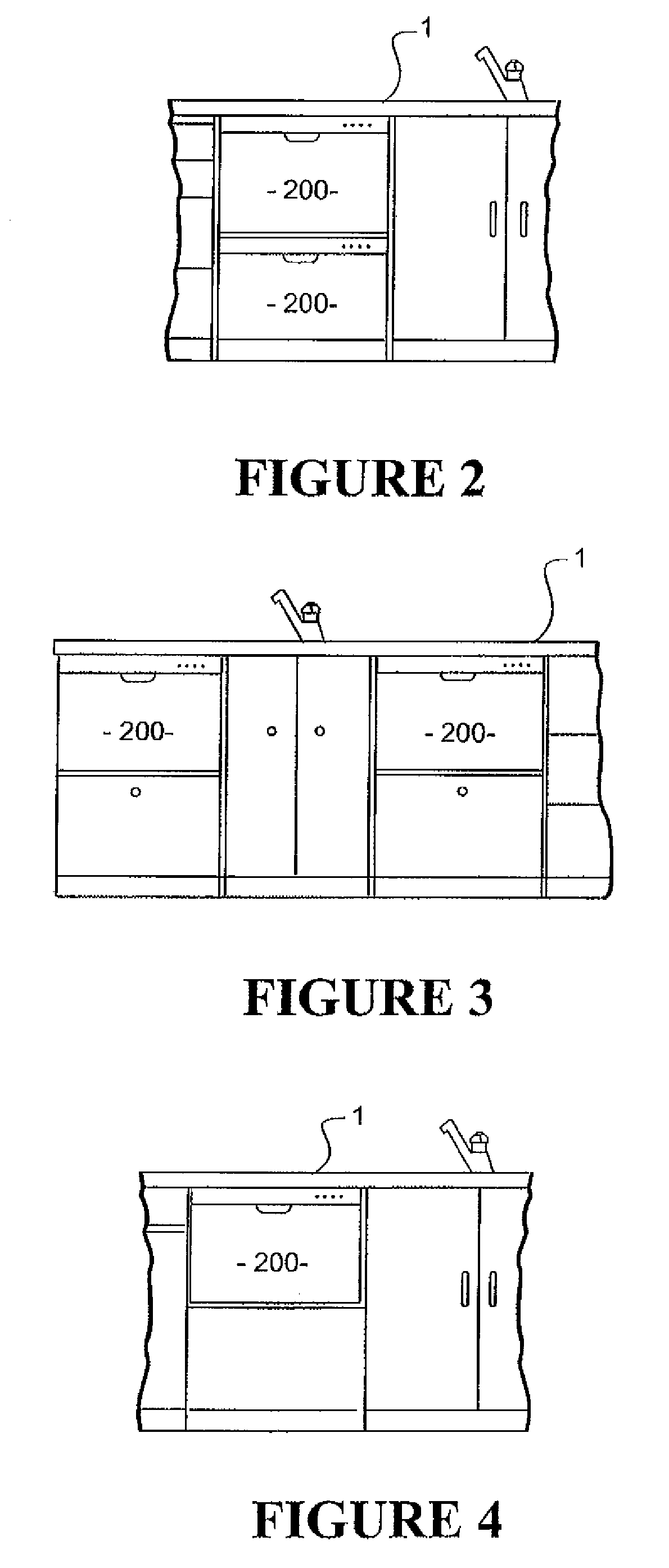
[0047]The washing appliance 200 is usually constructed with a height dimension approximately half that of conventional front-loading domestic washing appliances. In this form it can be used alone or as one of a n...


PUM


Abstract

A pump for washing appliance is described. The pump has a pump casing in which an impeller is located. The pump casing has an inlet and outlet, and an inlet conduit extending from the inlet at a small angle above the horizontal. The ceiling includes a downwardly extending dividing wall section extending radially from a central location to a side wall of the casing. The dividing wall is positioned between the inlet outlet. The ceiling incorporates a ramped surface rising around the central location, between the outlet side and the inlet side of the dividing wall. The ramped surface is higher adjacent the inlet side than the outlet side of the dividing wall section so that when the impeller is not rotating, air inside the pump chamber will rise up the ramped surface through the inlet and up the inlet conduit.

Description

BACKGROUND OF THE INVENTION[0001]1. Field of the Invention[0002]This invention relates to pumps used in washing appliances.[0003]2. Description of the Prior Art[0004]Drain pumps and wash pumps are used in washing appliances such as dishwashers. During the operation of a washing appliance air can be introduced into the pump housing. Air can build up to such an extent that liquid priming of the pump may be impeded or even prevented.[0005]A dishwasher drain pump is disclosed in U.S. Pat. No. 6,398,495. The drain pump is designed in a way that allows air trapped in the pump impeller chamber to be bled out of the pump soil pipe. However, the pump design does not allow all trapped air to be bled off, such that a level of air can remain trapped in the impeller chamber. The pump impeller is designed to overcome the level of air that can remain trapped, to allow adequate priming of the pump. While this drain pump operates satisfactorily, the efficiency of the pump can be affected by the leve...

Claims


Application Information

Patent Timeline
Patent Type & Authority Patents(United States)
IPC IPC(8): A47L15/42F04D29/66
CPCA47L15/4225F04D9/003F04D29/426A47L15/0084
Inventor COKER, CLINTONLAWRENCE, ROBHARGREAVES, GARETH
Owner FISHER & PAYKEL APPLIANCES LTD
Features
  • R&D
  • Intellectual Property
  • Life Sciences
  • Materials
  • Tech Scout
  • Unparalleled Data Quality
  • Higher Quality Content
  • 60% Fewer Hallucinations
Learn More