
Dynamic bar oriented user interface

a dynamic bar and user interface technology, applied in the field of communication devices, can solve the problems of becoming increasingly complex to create a single device that can excel at many different functions, pda device cannot make a good wireless telephone, wireless telephone device cannot make a good handheld personal digital assistant,

Active Publication Date: 2013-03-19
BLACKBERRY LTD
View PDF34 Cites 47 Cited by
  • Summary
  • Abstract
  • Description
  • Claims
  • Application Information

AI Technical Summary

Benefits of technology

The invention is about a way to control an apparatus using a graphical user interface. It includes a method for providing a dynamic bar on the main screen of the interface, with each bar associated with a different application or function of the apparatus. The dynamic bar has a pop-up interface that shows information about the application or function and can be used to activate or access the associated interface with a click. This makes it easier for users to quickly find and use the tools they need to control the apparatus.

Problems solved by technology

With the proliferation of communications services available on wireless mobile devices, it becomes increasingly complex to create a single device that can excel at many different functions.
Many critics claim that a wireless telephone device can never make a good handheld personal digital assistant (PDA) device and a handheld PDA device will never make a good wireless telephone.
Representing multiple services and functions to a user on a single wireless mobile device presents a number of challenges to the designer of a user interface, particularly a graphical user interface (GUI), for controlling the device.
Wireless devices are usually small relative to less portable computing devices such as laptops and desktop computers.
An application icon or information or text (e.g. name or title) describing the application is generally static and as such is not particularly useful for representing changing information associated with the application activated by the icon.
Representing current information to a user via a predominantly iconic GUI is difficult.
Further, organizing such information in a useful manner to permit a user to better control the device is also problematic.

Method used


Image

  • Dynamic bar oriented user interface
  • Dynamic bar oriented user interface
  • Dynamic bar oriented user interface

Examples


Embodiment Construction

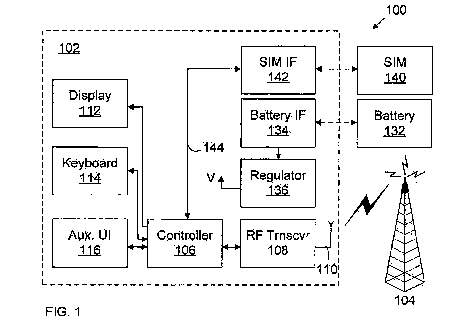
[0028]FIG. 1 is a block diagram of a communication system 100 which includes a mobile station 102 which communicates through a wireless communication network 104 symbolized by a station. Mobile station 102 preferably includes a visual display 112, a keyboard 114, and perhaps one or more auxiliary user interfaces (UI) 116, each of which are coupled to a controller 106. Controller 106 is also coupled to radio frequency (RF) transceiver circuitry 108 and an antenna 110.

[0029]Typically, controller 106 is embodied as a central processing unit (CPU) which runs operating system software in a memory component (not shown). Controller 106 will normally control overall operation of mobile station 102, whereas signal processing operations associated with communication functions are typically performed in RF transceiver circuitry 108. Controller 106 interfaces witch device display 112 to display received information, stored information, user inputs, and the like Keyboard 114, which may be a tele...


PUM


Abstract

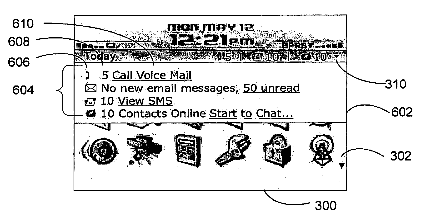
Method and user interface for controlling an apparatus are provided. At least one dynamic bar is provided for displaying on a main screen of a graphical user interface for controlling the apparatus. Each dynamic bar is associated with respective one or more interfaces for applications and / or functions provided by the apparatus and each dynamic bar has a pop-up interface for providing at least one of preview information determined from information managed by the applications and / or functions and links to invoke said respective interfaces.

Description

FIELD OF THE INVENTION[0001]The present invention relates generally to communication devices, and more particularly to a graphical user interface for controlling such devices.DESCRIPTION OF THE RELATED ART[0002]With the proliferation of communications services available on wireless mobile devices, it becomes increasingly complex to create a single device that can excel at many different functions. Many critics claim that a wireless telephone device can never make a good handheld personal digital assistant (PDA) device and a handheld PDA device will never make a good wireless telephone. It is also said that only teenagers are using Instant Messaging (IM) services or Short Message Services (SMS) to exchange messages with friends and acquaintances and that such users should get an entirely different wireless mobile device. However, many users of wireless handheld devices desire to have multiple services and functionality on a single device.[0003]Representing multiple services and funct...

Claims


Application Information

Patent Timeline
Patent Type & Authority Patents(United States)
IPC IPC(8): G06F3/048
CPCG06F3/0481G06F3/048G06F3/0482G06F16/9558G06F3/04817G06F3/04842G06F3/04847
Inventor SCOTT, SHERRYL LEE LORRAINE
Owner BLACKBERRY LTD
Learn More