Push broom head

a broom head and sweeping technology, applied in the field of broom heads, can solve the problems of reducing the service life and effectiveness of the broom, wasting the effectiveness of a significant number of bristles, and not being able to operate effectively on a wide range of surfaces, so as to reduce the likelihood of sweeping, prevent or reduce the likelihood, and reduce the effect of friction resistan

Inactive Publication Date: 2013-03-26
CFS BRANDS LLC
View PDF16 Cites 13 Cited by
  • Summary
  • Abstract
  • Description
  • Claims
  • Application Information

AI Technical Summary

Benefits of technology

[0047]The present invention includes a certain inherent adaptation to surfaces of various types. For instance, if the surface being swept is smooth, and therefore has less frictional resistance to the sweeping action, the longer, finer tufts 32B will perform the majority of the sweeping work. In such an instance, the shorter, coarser tufts 32A will act to help support the broom head 30 and prevent or reduce the likelihood that the user will apply excessive force to the finer bristles in the finer tufts 32B, which could reduce their effectiveness and cause premature wear. Similarly, in cases where the surface being swept is rougher, and therefore has a greater frictional resistance to the sweeping action, the finer tufts 32B in the rear of the broom head 30 will readily deflect back and more of the cleaning or sweeping force will be directed to the coarser tufts 32A, which will typically work more effectively on such a surface.
[0048]In a preferred embodiment of the invention, a plurality of rows of tufts of finer bristles 32B are present. Further the lengths of the bristles and / or the associated angles of attack for each row of finer tufts 32B is preferably varied. Such variance or dual variances, which may be implemented on a row-by-row basis, can provide a customized configuration that permits the broom head 30 to sweep debris from a plurality of different angles with various surface tensions.
[0049]As illustrated in the preferred embodiments shown in FIGS. 2-4, the bristle lengths of the tufts of finer bristles 32A can be intentionally increased slightly (as shown) or substantially with each subsequent row—taken in a rearward direction from the leading edge 16. Further, the angles of attack of the bristles of the finer tufts 32A—taken from the central vertical axis A—may also be increased for each such subsequent row, particularly increasing in the trailing rows of finer tufts 32B that are positioned furthest from the leading edge 16. If included, an inclined surface 20 positioned adjacent to the trailing edge 17 can be used in connection with the rooting system in the base 10 to provide finer tufts 32B that extend therefrom and, when in operation, are less vertical and more horizontal to the surface being swept. Such an orientation can provide extra relief to a downward sweeping motion and a greater dragging effect for sweeping particles of debris that pass beyond the more forward tufts of bristles.

Problems solved by technology

Single purpose broom designs have not been preferred, but are often the accepted approach because of the limited success of more versatile broom designs.
However, in many applications, this wastes the effectiveness of a significant number of the bristles, particularly the leading edge of softer / finer bristles.
However, while such designs may work on a wider range of particles, they do not necessary operate effectively on a wide range of surfaces, which can range from smooth to quite rough.
It also has been found that such angled sweeping action can produce excessive and premature wear on the forward bristles, thereby reducing both the service life and effectiveness of the broom.
Moreover, without a varying degree of “preload” (which is generally accomplished by the angle of the trim in conjunction with the angle of the handle of the broom dictated by the angle of the hole in the block), a broom head may not be effective for reaching into many surface irregularities.
Further, conventional dual-bristle-type broom heads (such as the type disclosed in the '758 Lay Patent) often have a limited range of applications that may not provide the desired range or degree of versatility.
Commonly, such broom heads are limited to single or narrow bands of forward rows of coarser, non-angled bristles.
In some instances, such as when a great deal of debris of various sizes is being swept, the single or narrow bands of coarser rows may fail to catch or move the type of debris that it is intended to collect.
Such conventional broom heads commonly do not employ reduced-diameter bristle fibers.

Method used


Image

  • Push broom head
  • Push broom head
  • Push broom head

Examples


Embodiment Construction

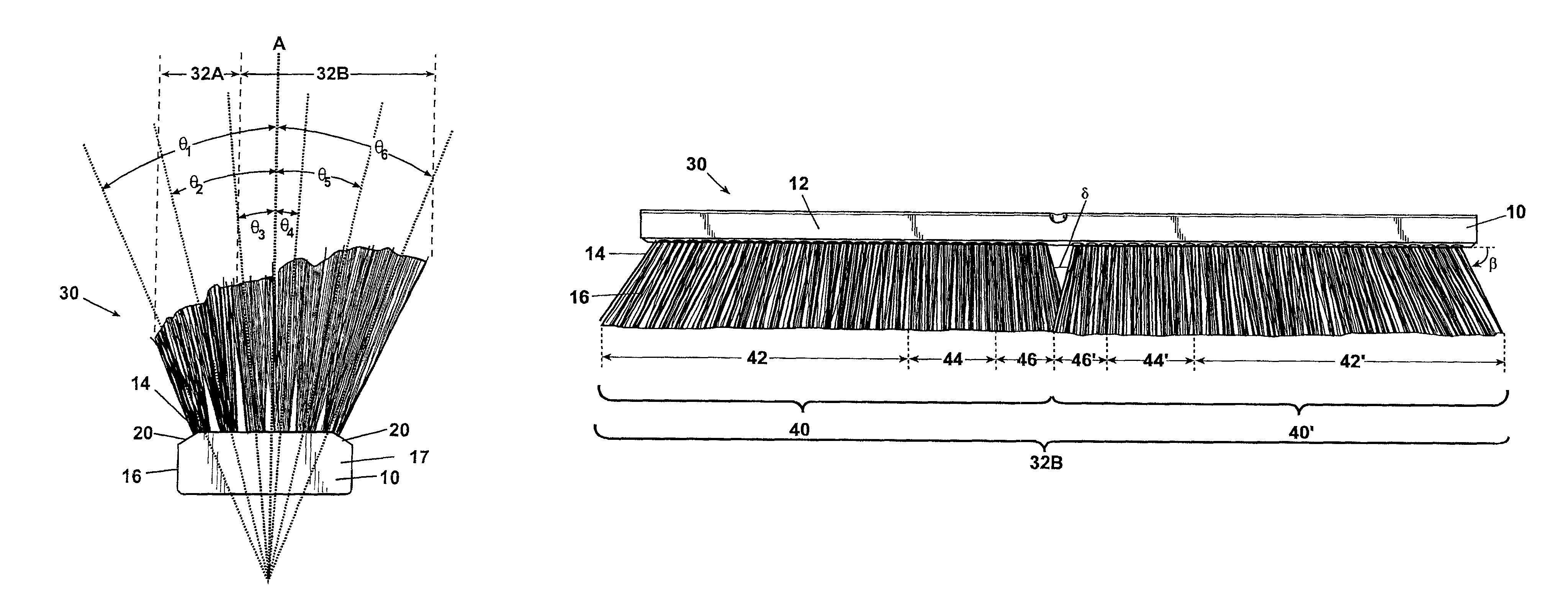
[0021]Referring now to the drawings, the preferred embodiments of the present invention are described in detail. Turning first to FIG. 1, there is shown a bottom view of a push broom head base 10. Base 10 includes an upper surface 12 (not visible in this figure), a lower surface 14, a leading edge 16, a trailing edge 17, and a plurality of seats 18.

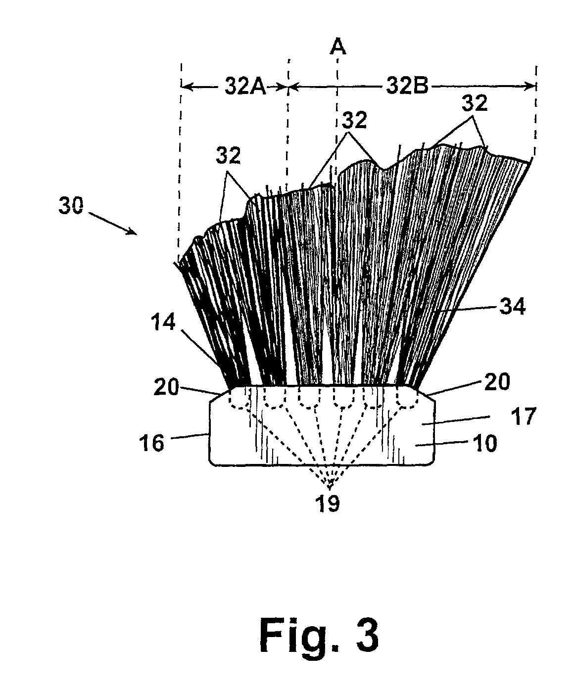
[0022]The base 10 is preferably oblong or rectangular in shape. However, in carrying out the present invention, the shape of the base 10 is not so limited and may be modified in various ways without departing from the present invention. As shown in FIG. 1, but perhaps better illustrated in FIG. 2, the base 10 may, if desired, include one or more chamfered segments or inclined portions 20. When employed, such inclined portions 20 can provide certain advantages—as discussed further herein.

[0023]As illustrated, base 10 includes a plurality of attachment points or seats 18. The seats, which are preferably drilled and are generally round or ov...


PUM


Abstract

A push broom head is provided having a substantially rigid base, leading edge, upper and lower surface, central vertical axis, plurality of rows of seats, and a plurality of tufts of bristles. The head includes a leading edge row(s) of tufts of a first type closest the leading edge and a plurality of rows of a second type. The length of the second type of tuft bristles is longer than the length of the first type and the number of rows of tufts of the second type exceeds the first type. The axis of each tuft forms an angle relative to the base's central vertical axis. Preferably, when not in contact with the sweeping surface, the angle of attack of the second type of bristles differs by row and/or the angle of the leading row of tufts exceeds 10 degrees in a forward direction relative to the central vertical axis.

Description

FIELD OF THE INVENTION[0001]The present invention relates generally to broom heads. More particularly, the present invention relates to an improved push broom head that includes a plurality of rows of two or more types of bristles with different lengths and / or angles of attack.BACKGROUND OF THE INVENTION[0002]Broom heads of the push type are commonly known. Further, such broom heads are used on many diverse floors and other surfaces for both residential and commercial applications.[0003]Typically, the design of a push broom head is approached with one or more specific applications in mind. Single purpose broom designs have not been preferred, but are often the accepted approach because of the limited success of more versatile broom designs. Design considerations generally take into account the type of debris that is anticipated in use—such as fine or coarse particles of dirt or debris—and the roughness or smoothness of the surface to be swept. In an effort to avoid the need to use m...

Claims


Application Information

Patent Timeline
Patent Type & Authority Patents(United States)
IPC IPC(8): A46B15/00
CPCA46B9/025A46B9/028A46B2200/302
Inventor LARSON, TIMOTHY J.
Owner CFS BRANDS LLC
Why Eureka
Try Eureka