Interlocking panel system

a technology of interlocking panels and panels, which is applied in the field of panel systems, can solve the problems of gap deflecting away from the building at the seam section, and irregular seam sections between two adjacent panels, and achieves the effect of less apparent seams and a smoke-free seam

Active Publication Date: 2013-03-26
ROYAL GROUP
View PDF85 Cites 19 Cited by
  • Summary
  • Abstract
  • Description
  • Claims
  • Application Information

AI Technical Summary

Benefits of technology

[0010]In view of the foregoing, it is a feature of the embodiments described herein to provide a system of panels that provides an improved end-to-end seam section with the outer surfaces of the joined panels providing a generally planar surface. In various embodiments, adjacent panels in a siding system may overlap and interlock at a seam section in a secure fashion. Once interlocked, the siding panels may expand and contract without causing a bulge or gap at the seam section. One benefit of siding panel assembly may be that the expansion and contraction associated with the individual siding panels is transferred to the ends of the assembly, rather than the end of each individual siding panel. Another benefit of the siding panel assembly of the embodiments is that it allows for a smoother seam between individual panels, so that it is less apparent from all viewing angles, unlike vinyl siding where the pieces are overlapped, to allow for expansion and contraction.

Problems solved by technology

This expansion and contraction may cause irregularities in the seam section between two adjacent panels.
For example, if adjacent abutting panels expand, the ends of the adjacent panels may expand toward each other, causing them to deflect away from the building at the seam section.
If adjacent abutting panels contract, the ends of the panels may draw away from each other, resulting in a gap at the seam section.
The gapping created by expansion or contraction of the siding panels may leave openings that can be unsightly, and leave the siding and building surface susceptible to damage from the elements.
However, the overlapping region leaves an undesirable visible seam.
In addition, the gap between the two overlapping sections allows water, air, and insects to pass which may cause damage to the siding panels or the underlying building surface.
Furthermore, where the overlapping region is unfastened, the ends of the siding panels can separate, further exacerbating these issues.
However, the use of separate connector pieces complicates the installation and assembly of the siding panels.

Method used


Image

  • Interlocking panel system
  • Interlocking panel system
  • Interlocking panel system

Examples


Embodiment Construction

[0030]The following description is intended to convey a thorough understanding of the embodiments by providing a number of specific embodiments and details involving a siding panel assembly. It is understood, however, that the invention is not limited to these specific embodiments and details, which are exemplary only. It is further understood that one possessing ordinary skill in the art, in light of known devices, systems and methods, would appreciate the use of the invention for its intended purposes and benefits in any number of alternative embodiments.

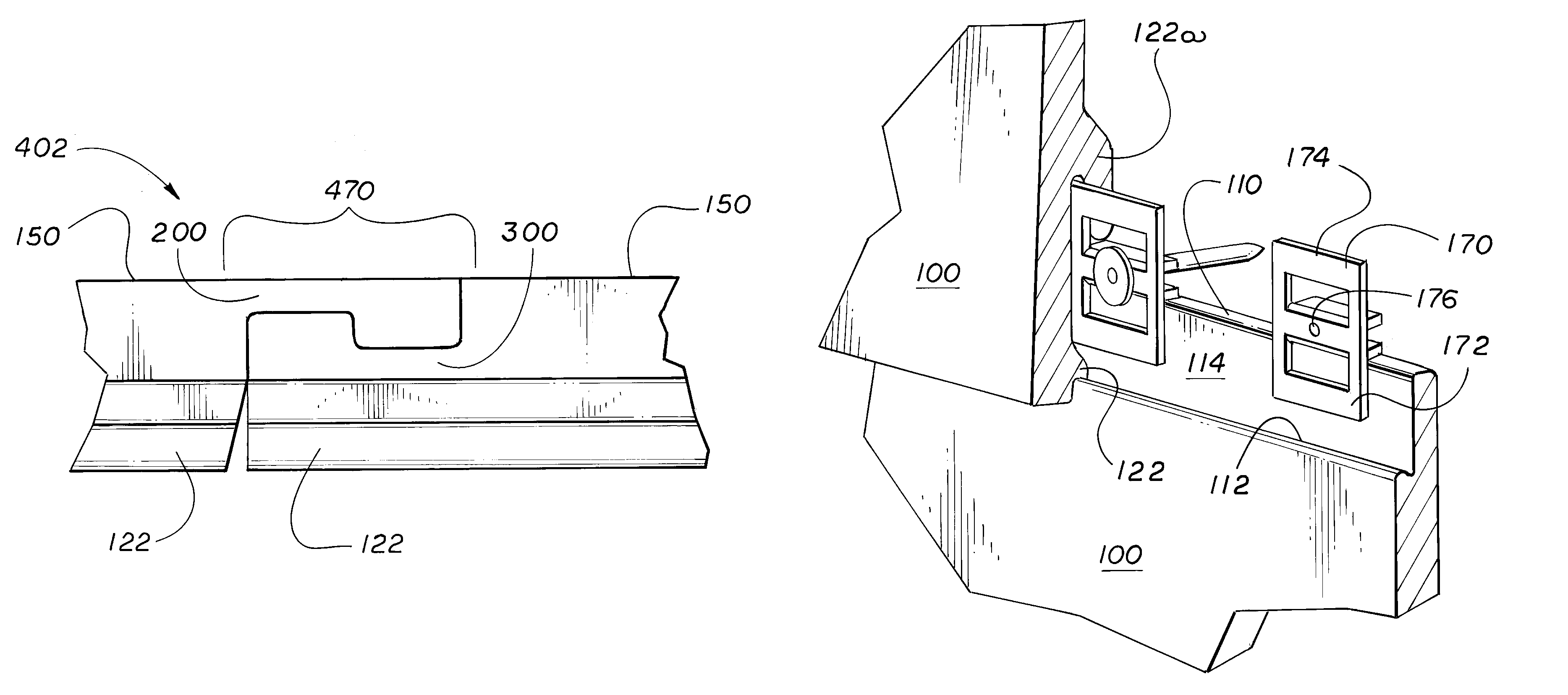
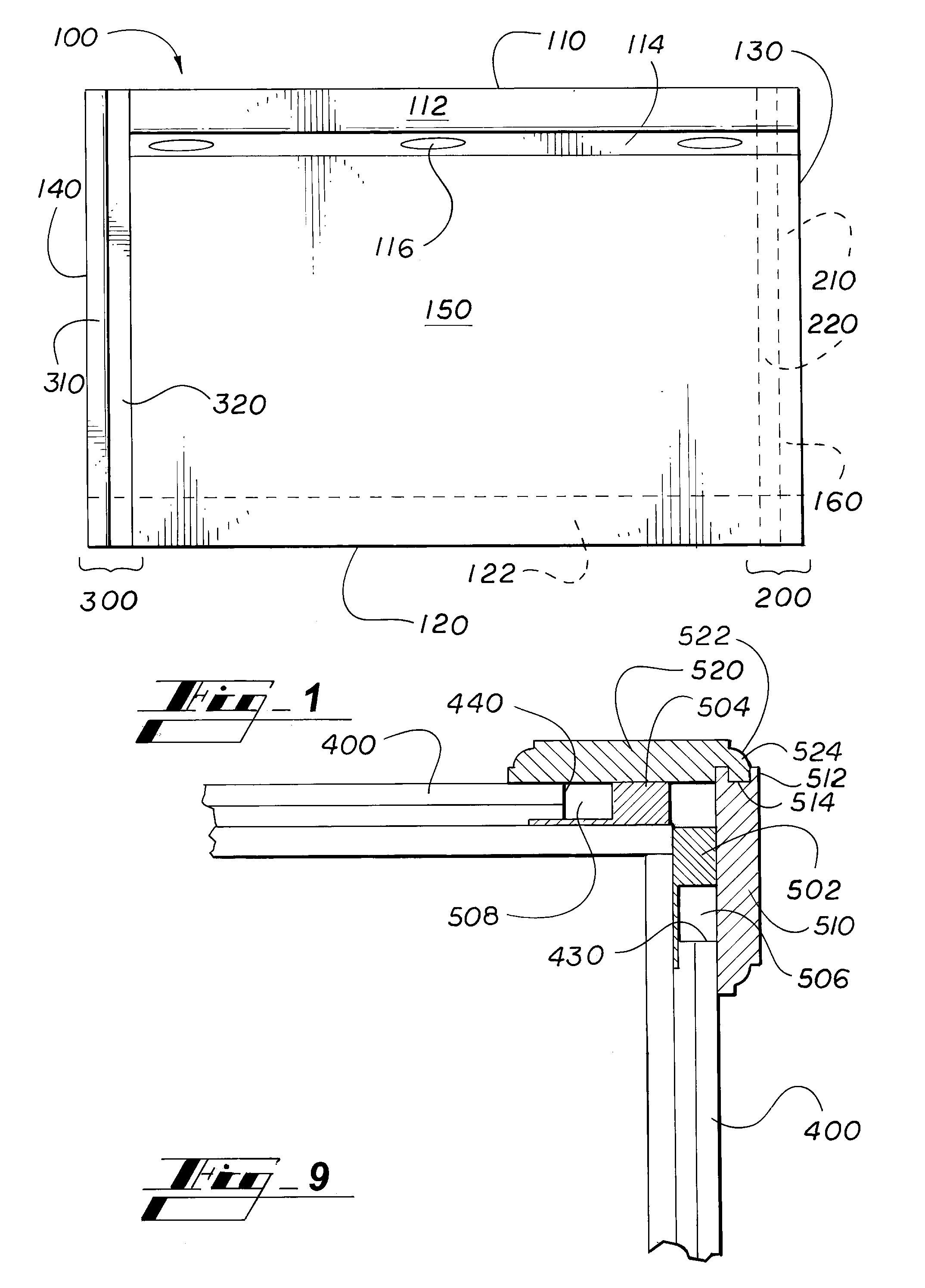
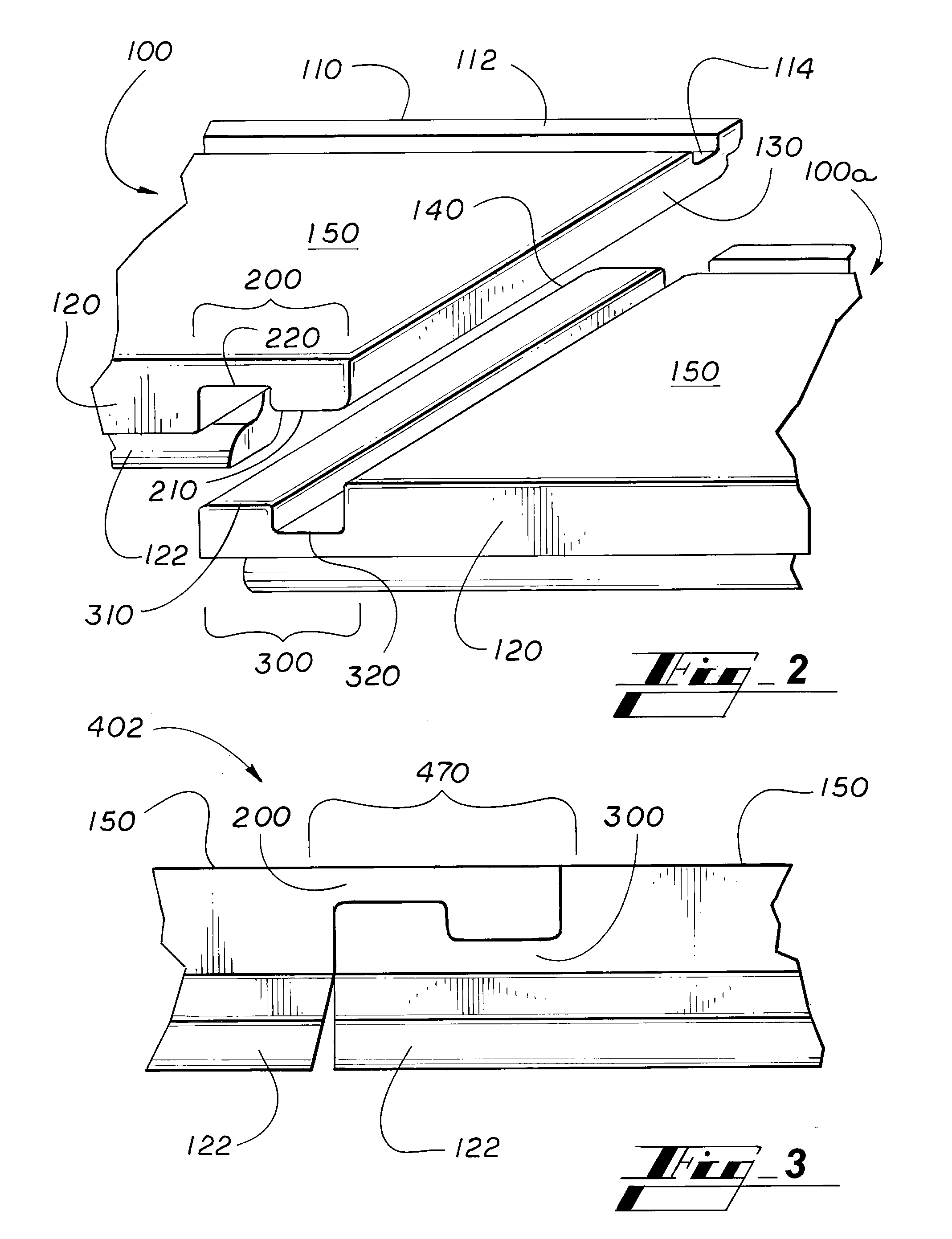
[0031]Generally speaking, panel systems of the present invention are generally flat sections used in building, construction and other applications, including in walls, siding, flooring, tiling, shelving, furniture and like. In one described but non-limiting embodiment, a panel system of the invention includes siding panels that have a plurality of horizontally adjacent siding panels that are interlocked on their vertical ends to p...


PUM

PropertyMeasurementUnit
widthaaaaaaaaaa
interlocking shapesaaaaaaaaaa
temperatureaaaaaaaaaa

Abstract

A panel system includes elongated panels coupled together at a seam portion with respective interlocking portions at corresponding vertical ends to provide a substantially planar surface. In siding panel systems, joined siding panels are provided in vertically arranged rows that further couple together along adjacent horizontal edges of the respective rows of siding panels.

Description

CROSS-REFERENCE TO RELATED APPLICATION[0001]The present application claims the benefit of priority of U.S. Provisional Application No. 61 / 299,383 filed Jan. 29, 2010, which is incorporated herein by reference.BACKGROUND[0002]1. Field of the Art[0003]The present invention relates to panel systems, such as generally flat sections used in building, construction and other applications, including in walls, siding, flooring, tiling, shelving, furniture and like. In non-limiting embodiments the present invention provides a system of interlocking siding panels and a method of making interlocking siding panels.[0004]2. Description of Related Art[0005]Vinyl and metal siding panels, such as those used to cover the exterior of a building, generally are formed as single lap panels that extend horizontally across the building. In cases where a single panel is not long enough to extend across an entire surface of a building, multiple panels may be positioned horizontally adjacent to one another. H...

Claims


Application Information

Patent Timeline
Patent Type & Authority Patents(United States)
IPC IPC(8): E04F13/073E04F13/076
CPCE04F13/076E04C2/38E04F13/073E04C2/20E04F13/0894E04F13/18E04F13/0864E04F13/0889E04F2201/026
Inventor MITCHELL, STEVEN A.STAFFORD, BRIAN L.KING, NOEL E.OLINGER, RODNEY L.
Owner ROYAL GROUP
Why Eureka
Try Eureka