

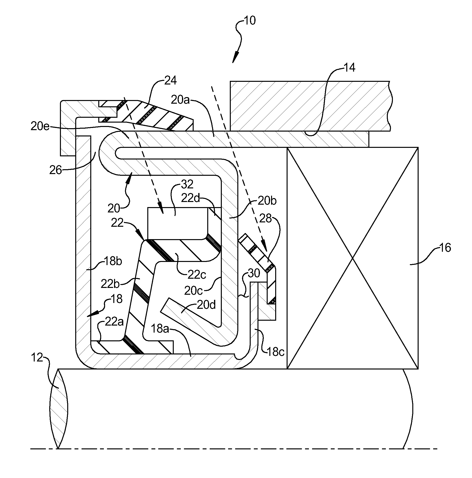
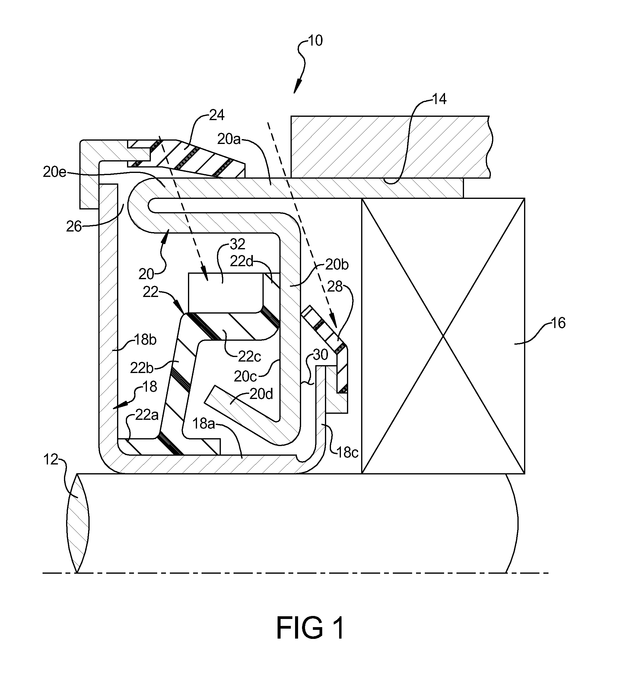
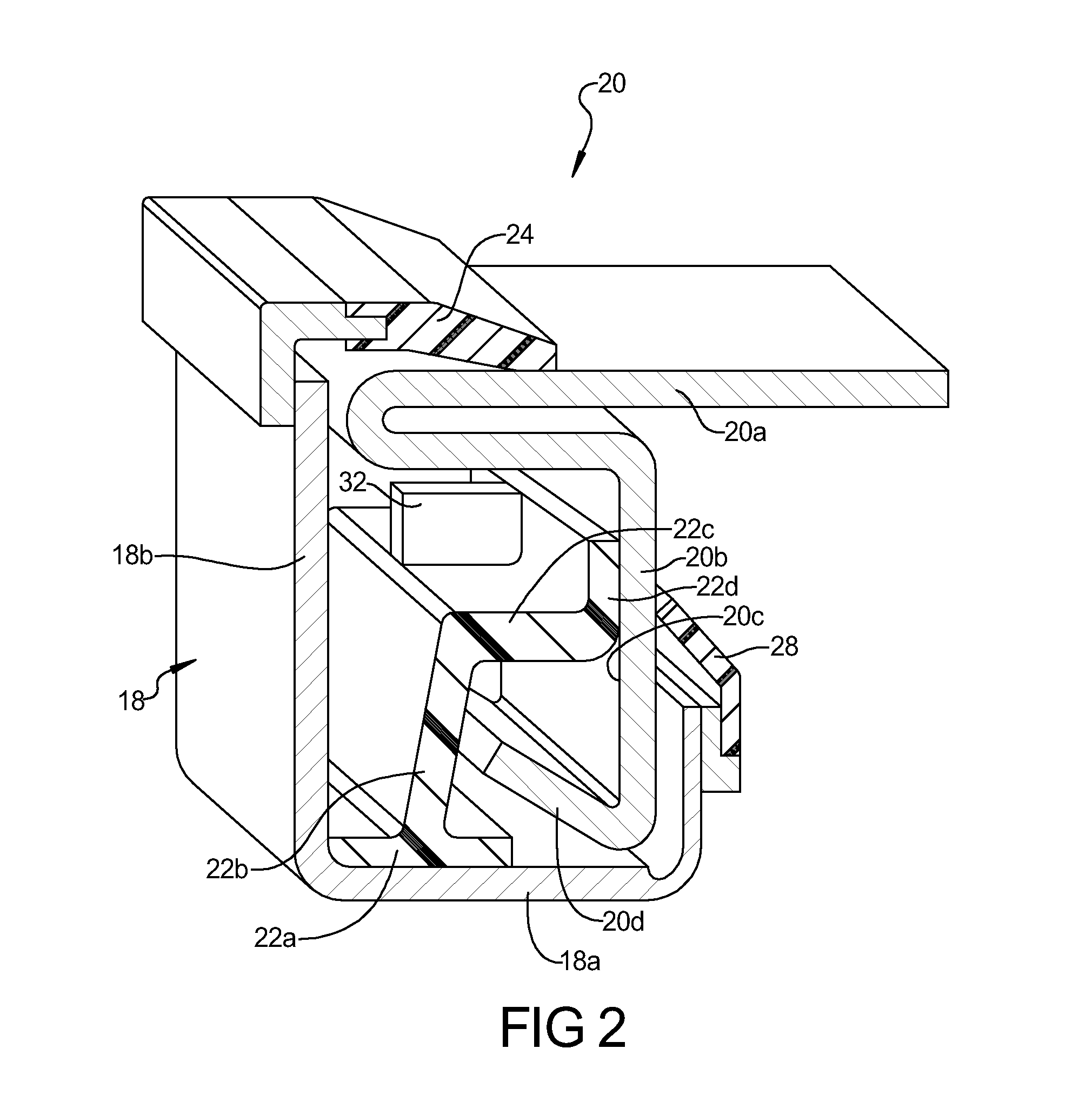
Zero torque membrane seal
a membrane seal and zero-torque technology, applied in the direction of engine seals, mechanical equipment, engine components, etc., can solve the problems of adding torque load and cost to the seal design, affecting the performance of the system, etc., to prevent grease loss, add torque load, and hinder the system's performance
- Summary
- Abstract
- Description
- Claims
- Application Information
AI Technical Summary
Benefits of technology
Problems solved by technology
Method used
Image

Examples
Embodiment Construction
[0016]Example embodiments will now be described more fully with reference to the accompanying drawings.
[0017]Example embodiments are provided so that this disclosure will be thorough, and will fully convey the scope to those who are skilled in the art. Numerous specific details are set forth such as examples of specific components, devices, and methods, to provide a thorough understanding of embodiments of the present disclosure. It will be apparent to those skilled in the art that specific details need not be employed, that example embodiments may be embodied in many different forms and that neither should be construed to limit the scope of the disclosure.
[0018]The terminology used herein is for the purpose of describing particular example embodiments only and is not intended to be limiting. As used herein, the singular forms “a”, “an,” and “the” may be intended to include the plural forms as well, unless the context clearly indicates otherwise. The terms “comprises,”“comprising,”“...
PUM
 Abstract
Description
Claims
Application Information