Method and system for providing a transducer having dual, ABS recessed auxiliary poles on opposite sides of a main pole with non-magnetic spacer adjoining back portion of main pole and positioned between auxiliary poles

Active Publication Date: 2013-03-26
WESTERN DIGITAL TECH INC
View PDF24 Cites 171 Cited by
  • Summary
  • Abstract
  • Description
  • Claims
  • Application Information

AI Technical Summary

Benefits of technology

[0003]A method and system for providing a magnetic recording head is described. The magnetic recording head has an air-bearing surface (ABS) configured to reside in proximity to a media during use. The magnetic recording head includes a main pole, a first auxiliary pole, a second auxiliary pole, a backgap, a nonmagnetic spacer, and at least one coil. The main pole includes a pole tip occupying a portion of the ABS and a back edge distal from the ABS. The first auxiliary pole has a first front recessed from the ABS and a first back portion. The first auxiliary pole is magnetically coupled with the main pole. The second auxiliary pole has a second front recessed from the ABS and a second back portion. A portion of the main pole distal from the ABS resides between the first auxiliary pole and the second auxiliary pole. The second auxiliary pole is magnetically coupled with the main pole. The backgap magnetically couples the first back portion of the first auxiliary pole with the second back portion of the second auxiliary pole. The nonmagnetic spacer adjoins the back edge of the main pole and is between the first auxiliary pole and the second auxiliary pole. The coil(s) energize the main pole.

Problems solved by technology

Although the conventional PMR transducer 10 may function, it may be inefficient.

Method used


Image

  • Method and system for providing a transducer having dual, ABS recessed auxiliary poles on opposite sides of a main pole with non-magnetic spacer adjoining back portion of main pole and positioned between auxiliary poles
  • Method and system for providing a transducer having dual, ABS recessed auxiliary poles on opposite sides of a main pole with non-magnetic spacer adjoining back portion of main pole and positioned between auxiliary poles
  • Method and system for providing a transducer having dual, ABS recessed auxiliary poles on opposite sides of a main pole with non-magnetic spacer adjoining back portion of main pole and positioned between auxiliary poles

Examples


Embodiment Construction

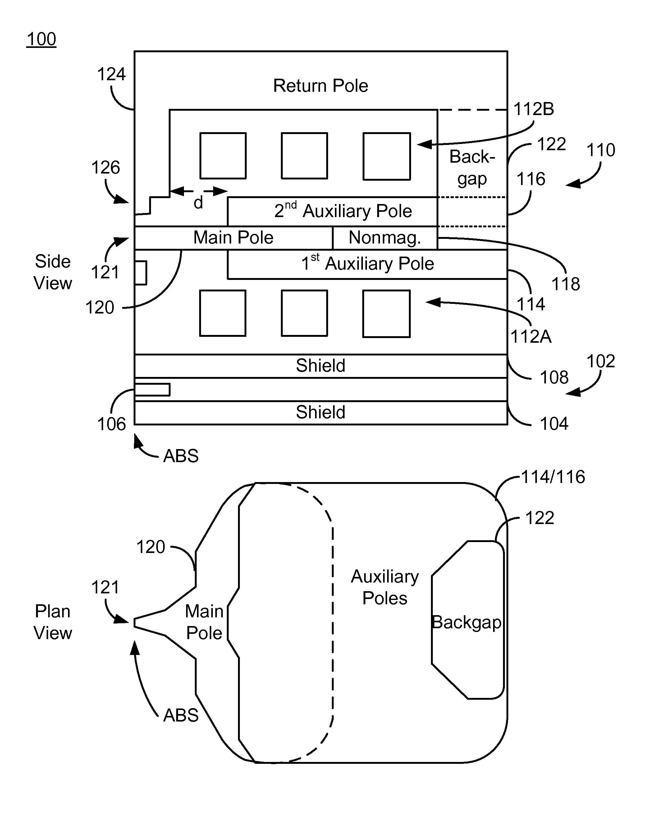
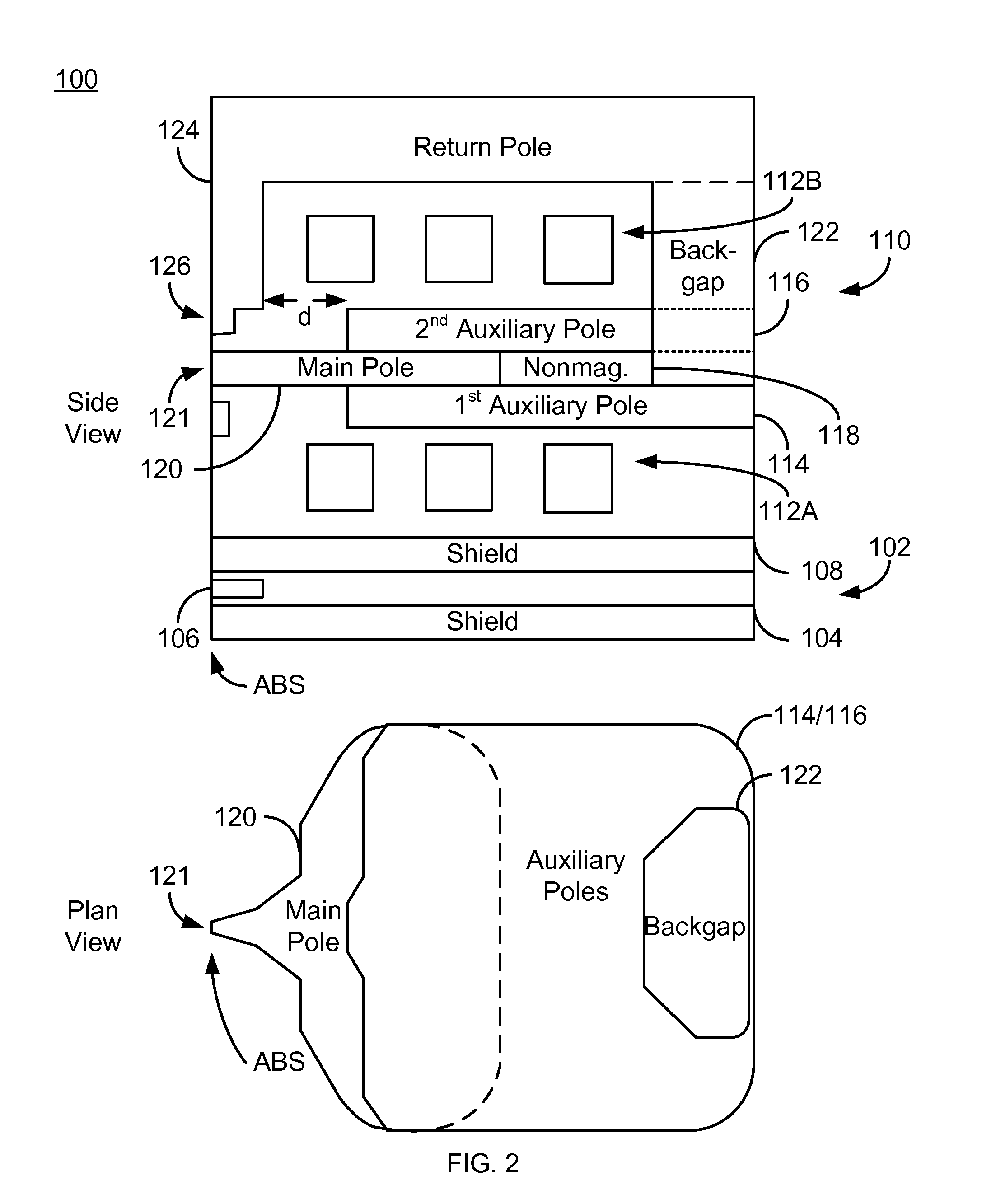
[0010]FIG. 2 is a diagram depicting side and plan views of a portion of a magnetic recording head 100 that may reside on a slider (not shown) in a disk drive that also include media (not shown). For clarity, FIG. 2 is not to scale. Further, only some of the components depicted in the side view are also shown in the plan view. In some embodiments, the magnetic recording head 100 is a PMR head. Consequently, FIG. 2 is described in the context of a PMR head. For simplicity not all portions of the PMR head 100 are shown. In addition, although the PMR head 100 is depicted in the context of particular components other and / or different components may be used. Further, the arrangement of components may vary in different embodiments. The PMR head 100 has an ABS configured to reside close to a media (not shown) during operation. The PMR head 100 is a merged head including a read transducer 102 and a write transducer (PMR transducer) 110. The read transducer 102 includes shields 104 and 108 as...


PUM

PropertyMeasurementUnit
thicknessesaaaaaaaaaa
distanceaaaaaaaaaa
distanceaaaaaaaaaa

Abstract

A method and system for providing a magnetic recording head is described. The magnetic recording head has an ABS configured to reside in proximity to a media during use. The magnetic recording head includes a main pole, first and second auxiliary poles, a backgap, a nonmagnetic spacer, and at least one coil. The main pole includes a pole tip occupying a portion of the ABS and a back edge distal from the ABS. Each auxiliary pole has a front recessed from the ABS and a back portion. A portion of the main pole distal from the ABS resides between the auxiliary poles. The auxiliary poles are magnetically coupled with the main pole. The backgap magnetically couples the back portions of the auxiliary poles. The nonmagnetic spacer adjoins the back edge of the main pole and is between the auxiliary poles. The coil(s) energize the main pole.

Description

BACKGROUND[0001]FIG. 1 depicts a portion of a magnetic recording transducer 10, such as a perpendicular magnetic recording (PMR) transducer. For clarity, FIG. 1 is not to scale. The conventional PMR transducer 10 includes a shield 12, main pole 14, auxiliary pole 16, coils 18 and return pole / back gap 20. Although depicted as above the main pole 14 (with respect to the substrate that is not shown), the auxiliary pole 16 might be below the main pole 14. In operation, a current is driven through the coil(s) 18 to energize the main pole 14. As a result, the mail pole 14 writes to the media (not shown).[0002]Although the conventional PMR transducer 10 may function, it may be inefficient. The trend in magnetic recording is to higher areal densities and higher data rates. For example, areal densities exceeding 550 Gb / in2 and data rates of over 2 Gb / s are desired. Such high data rates require the conventional PMR transducer 10 to have a reduced rise time for the field at high frequencies. H...

Claims


Application Information

Patent Timeline
Patent Type & Authority Patents(United States)
IPC IPC(8): G11B5/147
CPCG11B5/1278G11B5/3116Y10T29/49044
Inventor LI, ZHANJIEBAI, ZHIGANGLIU, FENGWANG, YUGANG
Owner WESTERN DIGITAL TECH INC
Why Eureka
Try Eureka