Fall detection system
a detection system and technology of a fall detection device, applied in the field of fall detection devices, can solve the problems of insufficient detection of an impact in acceleration data, insufficient positive identification of the occurrence of a fall, and the inability of detection systems to meet the needs of users, etc., to achieve the effect of improving reliability
- Summary
- Abstract
- Description
- Claims
- Application Information
AI Technical Summary
Benefits of technology
Problems solved by technology
Method used
Image
Examples
embodiment 1
Detection of a Free Fall Phase
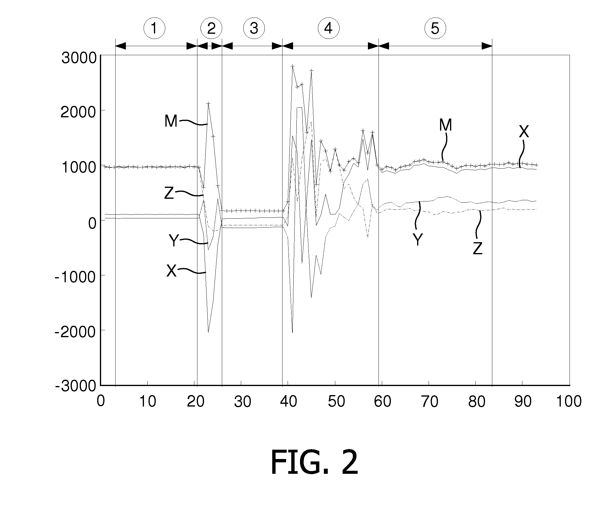
[0026]FIG. 2 represents the acceleration data X, Y, Z as measured during the fall of a sensor module 2, falling from a table onto the floor. FIG. 3 represents the acceleration data X, Y, Z as measured during the fall of a human, falling forward onto the floor. Both FIGS. 2 and 3 furthermore show the magnitude M that may for instance be calculated from:
M=√{square root over (X2+Y2+Z2)} (1)
or from:
M=|X|+|Y|+|Z| (2)
[0027]The acceleration data in FIG. 2 can be divided in five distinct phases, marked ① to ⑤:[0028]a first phase ①, during which the acceleration data X, Y, Z, M are substantially stable. This corresponds with the sensor module 2 lying still on the table;[0029]a second phase ②, during which the acceleration data X, Y, Z, M fluctuate in all three directions. This corresponds with the sensor module 2 being pushed over the edge of the table, so as to start its fall;[0030]a third phase ③, during which the acceleration data X, Y, Z remain substantial...
embodiment 2
Detection of One or More Full Rotations
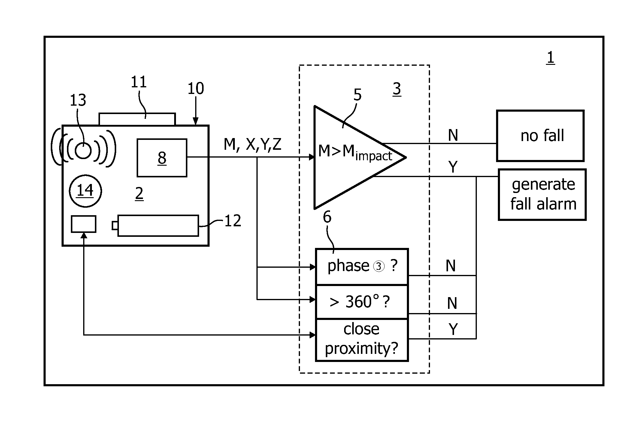
[0039]FIG. 5 schematically shows an embodiment of an alternative fall detection system 101 according to the invention, with alternative or additional second evaluation logic 106. Components that are similar to those of embodiment 1 have been identified with similar reference numerals, increased by 100. The second evaluation logic 106 makes use of the insight that small objects, such as a sensor modules 102, tend to make one or more full rotations (i.e. rotate over more than 360 degrees) when falling from a certain height. Persons, on the other hand, will usually not make such full rotations. This insight can therefore be used to distinguish between an accidental drop of the sensor module 102 and a human fall incident.
[0040]The detection system 101 according to FIG. 5 comprises a sensor module 102 and first evaluation logic 105 that may be similar to that described in FIG. 1. The sensor module 102 may be provided with one or more angular sensors...
embodiment 3
Detection of Close Proximity of Sensor Module and the User's Body
[0043]According to yet another embodiment of the invention, false alarms due to accidental falling of the sensor module may be prevented by having the second evaluation logic verify whether the sensor module is in close proximity of the human body (and thus likely to be worn) at the moment of an observed impact. To that end the second evaluation logic may for instance comprise a sensor, which may be accommodated in the sensor module and which is capable of sensing distortion of an electrical field caused by the user's body moving into or out of said field. A suitable sensor is for instance an electrical field sensor, as described in the article “Applying electrical field sensing to Human-Computer interfaces”, of authors T. G. Zimmerman, et al., published in IEEE, May 1995.
[0044]If, upon the detection of a potential fall incident (by for instance first evaluation logic as described in relation to the previous embodiment...
PUM
| Property | Measurement | Unit |
|---|---|---|
| gravity acceleration | aaaaa | aaaaa |
| rotation angle | aaaaa | aaaaa |
| acceleration | aaaaa | aaaaa |
Abstract
Description
Claims
Application Information
 - R&D
- Intellectual Property
- Life Sciences
- Materials
- Tech Scout
- Unparalleled Data Quality
- Higher Quality Content
- 60% Fewer Hallucinations
Browse by: Latest US Patents, China's latest patents, Technical Efficacy Thesaurus, Application Domain, Technology Topic, Popular Technical Reports.
© 2025 PatSnap. All rights reserved.Legal|Privacy policy|Modern Slavery Act Transparency Statement|Sitemap|About US| Contact US: help@patsnap.com


