Piling and drilling rig with foldable deflection apparatus

a deflection apparatus and drilling rig technology, applied in drilling machines, cranes, bulkheads/piles, etc., can solve the problems of high time and installation effort, no satisfactory design in which the transport length is achieved, and the increase of so as to reduce the transport length and reduce the transport height of the piling and drilling rig

Active Publication Date: 2013-04-02
LIEBHERR WERK NENZING
View PDF8 Cites 0 Cited by
  • Summary
  • Abstract
  • Description
  • Claims
  • Application Information

AI Technical Summary

Benefits of technology

[0011]It is therefore the object of the present invention to provide a piling and drilling rig in which a tiltable leader or mast having a deflection apparatus pivotally connected to the head end can be moved in as simple a manner as possible from an operating position into a working position in which the permitted transport height and a transport length which is as short as possible can be achieved.
[0012]This object is achieved in accordance with the invention in accordance with the description herein. In this piling and drilling rig, a leader and a deflection apparatus for the deflection of a rope are provided which is pivotally connected to the head of the leader in a manner pivotable between at least one transport position and at least one working position. The deflection apparatus is furthermore rotatable about an axis standing obliquely on the axis of extent of the leader. The deflection apparatus can be rotated due to the inventive rotatable pivotal connection to the upper end of the mast or leader such that the positioning of the deflection apparatus corresponds, in a transport position, to a position known in accordance with the prior art in which the deflection apparatus is folded rearwardly in a first step and the deflection apparatus is folded horizontally to the front in a separate, second step. The inventive rotation procedure of the deflection apparatus can in this respect also be effected relatively easily and fast under construction site conditions since the desired movement of the deflection apparatus can be adjusted in a single step. The release of separate screw connections or bolt connections of a second step such as is known from the prior art is furthermore omitted.
[0015]The design in accordance with the invention of the axis of rotation of the rotatably pivotally connected deflection apparatus allows it to be rotated in the transport position such that the transport height and the transport length of the piling and drilling rig can be influenced.
[0017]Provision can be made that the transport length of the piling and drilling rig can be reduced by the rotational movement of the deflection apparatus in the transport position. In the most favorable variant, the transport length of the piling and drilling rig can in this respect be reduced approximately by the length of the deflection apparatus. A desired or permitted transport length of the rig can be achieved in an extremely advantageous manner by the rotation in accordance with the invention of the deflection apparatus about the mast or leader.
[0018]In a further advantageous embodiment of the invention, the transport height of the piling and drilling rig can be reduced by the rotational movement of the deflection apparatus in the transport position. In this respect, the transport height of the piling and drilling rig can be reduced by the rotational movement of the deflection apparatus such that the topmost edge of the rig is formed either by a lowered part of the deflection apparatus or, in the most favorable case, by the upper edge of the leader or mast.
[0019]It is extremely advantageous that the transport length and the transport height of the piling and drilling rig can be reduced by the rotational movement of the deflection apparatus in the transport position in one step. The assembly procedure and / or dismantling procedure of a piling and drilling rig, i.e. the positioning of the rig from a working position into a transport position is thereby substantially simplified and accelerated. The permitted transport height of the piling and drilling rig can consequently be achieved by the rotational movement in accordance with the invention by simple means and a transport length can be achieved which is as short as possible, which becomes increasingly important with tight road conditions.

Problems solved by technology

It is disadvantageous in the construction apparatus of specifications EP 1 655 415 A1, U.S. Pat. No. 5,269,107 and DE 101 23 403 B4 that the transport length increases by a not insubstantial part by the folding of the deflection apparatus / mast head.
This procedure is, however, associated with a high time and installation effort since the mast head has to be released at a further screw connection or bolt connection to be able to fold it forward accordingly.
However, none of these approaches shows a satisfactory design in which a transport length is achieved which is as short as possible and the permitted transport height is observed.

Method used


Image

  • Piling and drilling rig with foldable deflection apparatus
  • Piling and drilling rig with foldable deflection apparatus
  • Piling and drilling rig with foldable deflection apparatus

Examples


Embodiment Construction

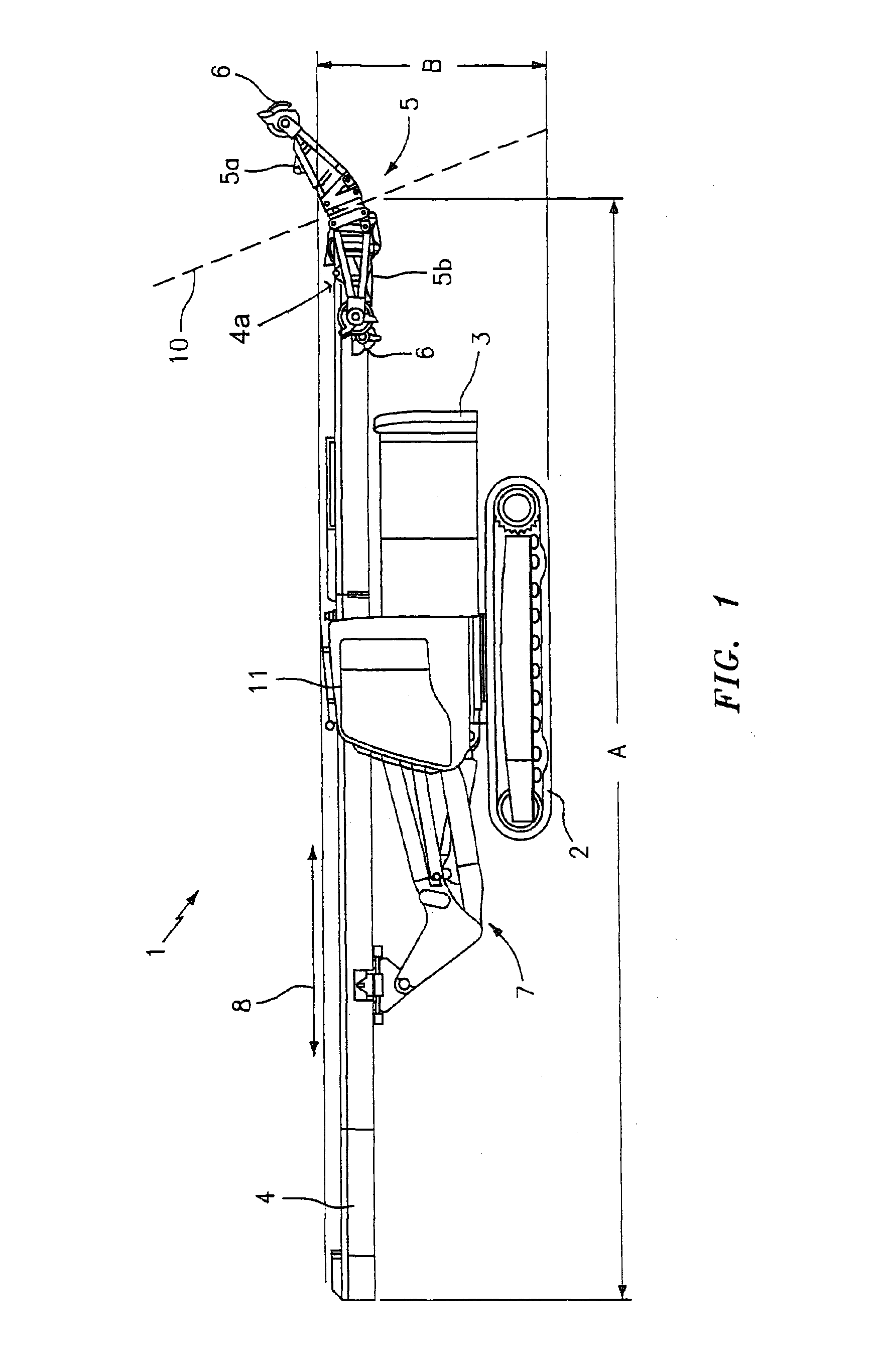
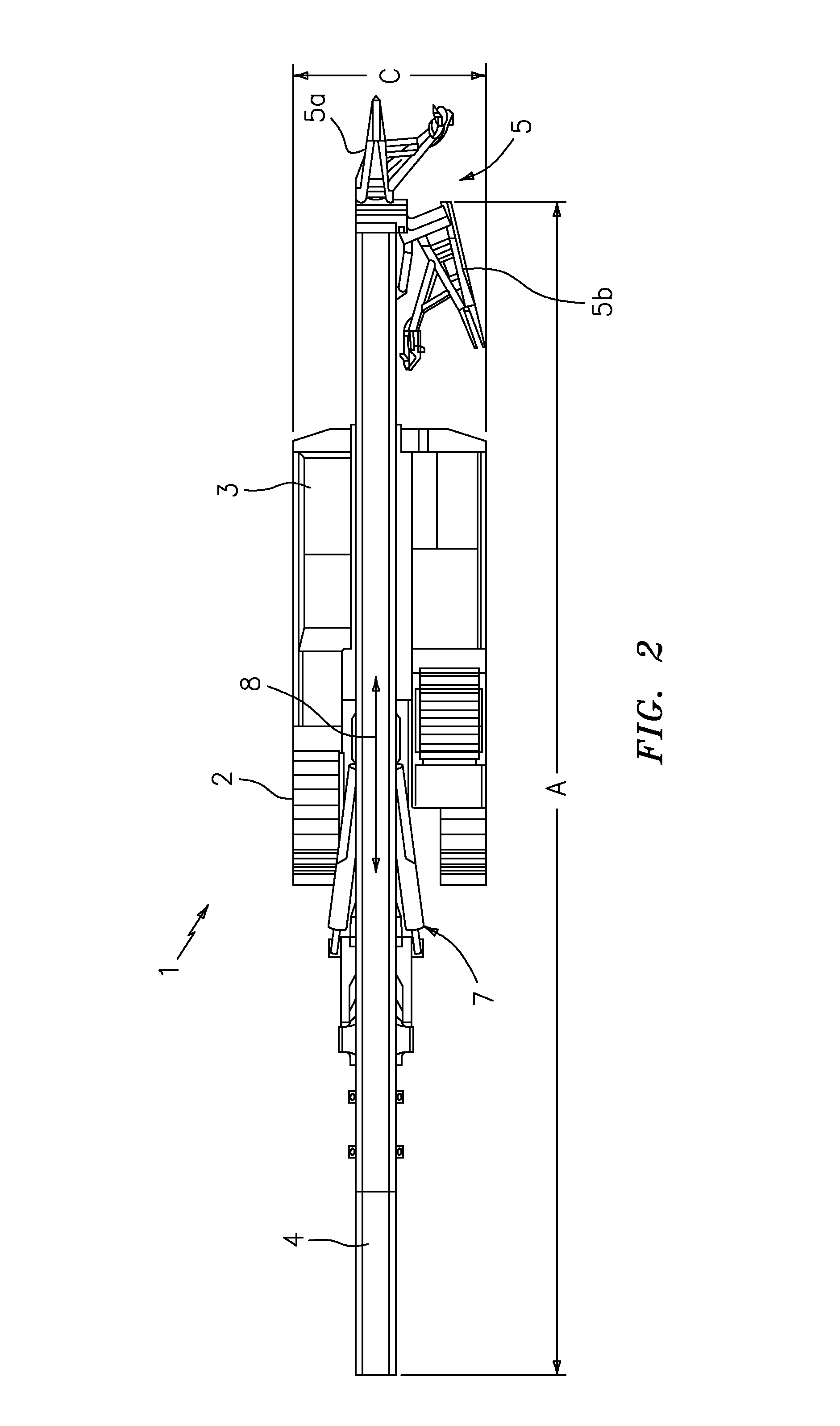
[0024]An embodiment of the piling and drilling rig in accordance with the invention is shown in FIGS. 1 and 2. The piling and drilling rig has an undercarriage 2 made as a crawler-mounted vehicle and a superstructure 3 arranged on the undercarriage 2. A leader 4 is mounted on the superstructure 3 with the aid of a holding apparatus 7. The leader 4 can be moved by means of the holding apparatus 7 from a vertically aligned working position, in which the longitudinal axis 8 of the leader 4 extends substantially vertically to the ground area and the leader 4 extends in front of the undercarriage 2 and the superstructure 3 of the piling and drilling rig 1, into a horizontally aligned transport position, in which its longitudinal axis 8 extends approximately horizontally with respect to the surface of the ground. The holding apparatus 7 is in this respect pivotally connected at one side to the leader 4 and at the opposite side to the superstructure 3 of the piling and drilling rig 1.

[0025...


PUM

PropertyMeasurementUnit
transport lengthaaaaaaaaaa
heightaaaaaaaaaa
transport heightaaaaaaaaaa

Abstract

The present invention relates to a piling and drilling rig having a leader, a deflection apparatus for the deflection a rope which is pivotally connected to the head of the leader in a manner pivotable between at least one transport position and at least one working position, with the deflection apparatus being rotatable about an axis standing obliquely on the axis of extent of the leader.

Description

BACKGROUND OF THE INVENTION[0001]The present invention relates to a piling and drilling rig having a leader, a deflection apparatus for the deflection of a rope which is pivotally connected to the head of the leader in a manner pivotable between at least one transport position and at least one working position.[0002]Generic piling and drilling rigs are in particular used in special underground engineering applications. Such rigs essentially comprise the so-called load bearing structure and the mast or leader with a rotary drive and Kelly bar. Piped or unpiped bores can be carried out in the ground with the help of these rigs and the ground material which accumulates can be brought to the surface. In particular in rigs which are used in special underground engineering, the mast or leader frequently has a substantial height, with a deflection apparatus being arranged at its upper end which has the underlying object of deflecting the hoist rope of the piling and drilling rig in the dir...

Claims


Application Information

Patent Timeline
Patent Type & Authority Patents(United States)
IPC IPC(8): E21B7/02E02D11/00B66C23/26
CPCB23K26/0807B23K26/10B23K26/0823B23K2201/003B23K26/082B23K2101/003
Inventor KOERTGE, STEPHANKOLLER, ALFRED
Owner LIEBHERR WERK NENZING
Why Eureka
Try Eureka