
Actuating device for selecting fixed gear ratios of a gear changing transmission

a gear shifting transmission and gear shift technology, which is applied in the direction of dashboard fitting arrangements, contact mechanisms, transportation and packaging, etc., can solve the problems of possible actuation lock in the transmission, gear shift status feedback, and possible operation errors

Active Publication Date: 2013-04-09
ZF FRIEDRICHSHAFEN AG
View PDF25 Cites 16 Cited by
  • Summary
  • Abstract
  • Description
  • Claims
  • Application Information

AI Technical Summary

Benefits of technology

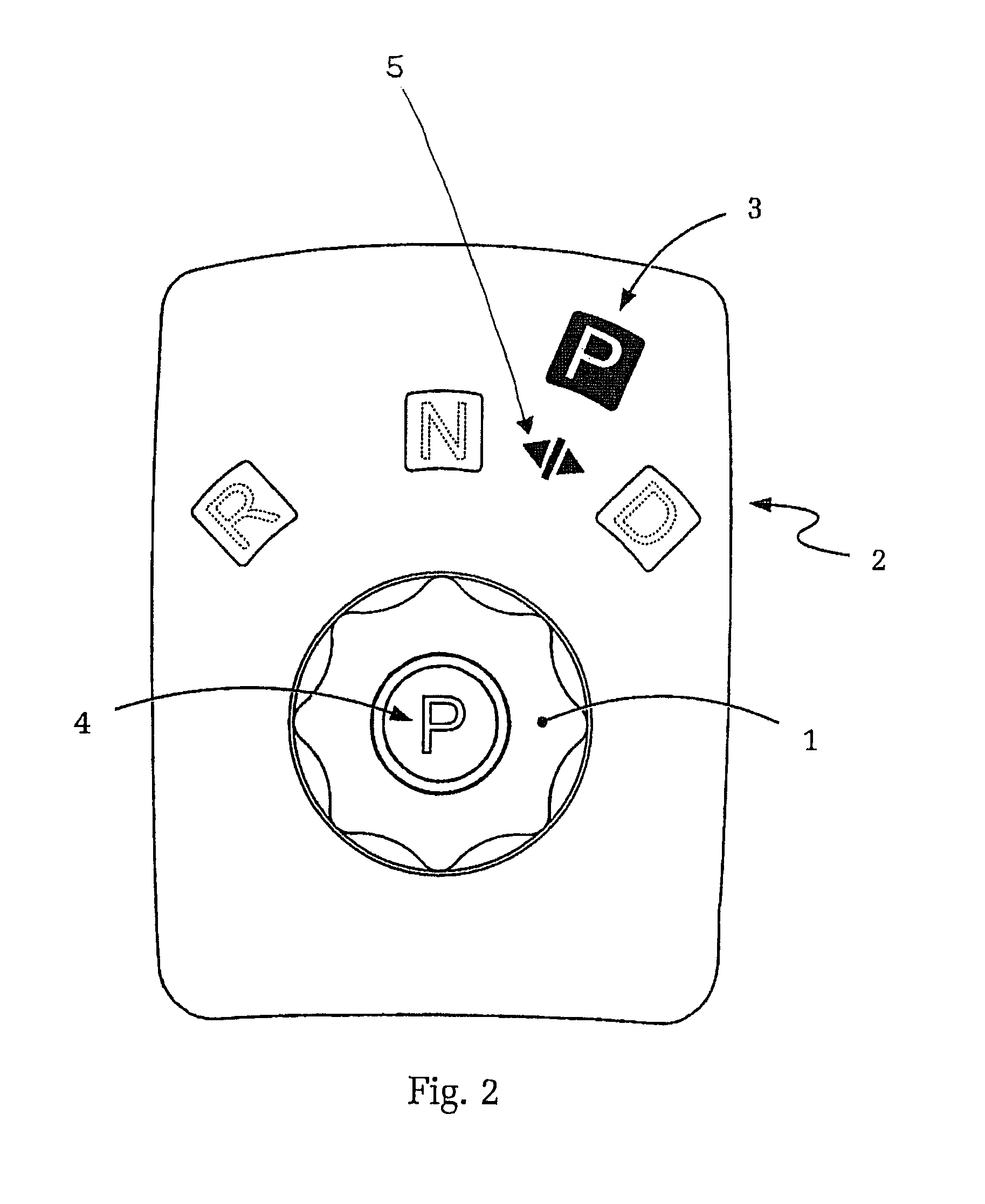
[0020]For instance, the park lock position of the gear selector device can be located between two drive step position, especially between the drive step position “N” and “D”. Hereby, the first advantage is short shift travel—with the engaged park lock—shifting from the park lock position selectively into one of the two selectable drive step positions “N” or “D”. In comparison to the state of the art, in which the park lock position is usually positioned outside of the area of the drive step positions, one first has to shift through the reverse gear drive position, when shifting from the park lock position into the drive position “N” or “D”, resulting in long shift travel which is detrimental in regard to ergonomics and an intuitive activation. Further, it is not required to block the park lock-shift position through actuation, as soon as the park lock became disengaged, in this configuration of the park lock shift position within the shift angle range of the other shift positions. Actually, in this case, it is sufficient to just logically eliminate the park lock-shift position from the shift scheme, meaning just to ignore any motion of the gear selector device in the control electronics.
[0025]In accordance with an alternative embodiment of the invention, the gear selector device is designed as monostable. A monostable designed gear selector device, for instance, an automatic-selector lever which spring-loaded and returns after each actuation back to the center position, initially has the advantage that no actuating device is necessary to match actuatorically, for the different cases, the selector lever position with the actually engaged drive step. The latter is, in the case of a defined-multistable gear selector device—i.e., with a conventional selector lever—especially required when automatically engaging the park lock through Auto-P so that the selector lever position matches, also in the case of Auto-P, again the transmission condition.
[0027]If, on the other hand, the park lock again is engaged, via actuation of the invented additional park lock-actuation device—or perhaps automatically via the Auto-P function—the gear display of the actuating unit can also be triggered in a way so that the display position, corresponding with the park lock position, is again activated and displayed. In addition, with a monostable gear selector device or a selector lever—by itself and known in the art—also an actuatorically adjustable end stop can be provided to limit, depending on the drive step and depending on other condition factors of the motor vehicle (like ignition ON, motor running, speed of the vehicle), the actuating range of the selector lever so that selection of the currently non-permitted shift steps is not only prevented but also signaled to the driver in a haptic mode by the actuating device.
[0042]Finally, another embodiment of the invention provides that the additional park lock-actuating device is also designed for an actuatoric actuation of an auxiliary brake. Hereby, the result is an advantageous integration of the function of the park lock and auxiliary brake, therefore, an additional contribution towards safety and ease of use. During each engagement of the park lock, the auxiliary brake can be activated as well completely protecting the vehicle from rolling away. The usual move on the hand brake or the actuating device for the auxiliary brake, respectively, can therefore be eliminated when turning off the vehicle.

Problems solved by technology

Also, possible actuating locks in the transmission become noticeable, due to the mechanical transfer, when operating the selector lever or the actuating devices.
Hereby, the haptic feedback, meaning the gear shift status feedback to the user, is basically limited to overcoming the locking of the actuating device.
In such actuating devices, however, which only require a short shift travel and shift forces, and which just provide minimal haptic feedback with regard to the shift state, operating errors are possible.
This will cause—at least at low speed—the park lock to engage and, therefore, maneuvering is unintentionally, and by surprise, interrupted.

Method used


Image

  • Actuating device for selecting fixed gear ratios of a gear changing transmission
  • Actuating device for selecting fixed gear ratios of a gear changing transmission
  • Actuating device for selecting fixed gear ratios of a gear changing transmission

Examples


Embodiment Construction

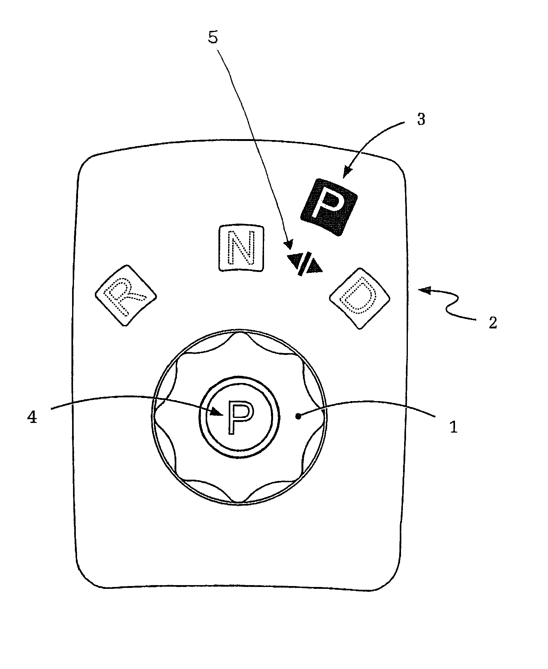
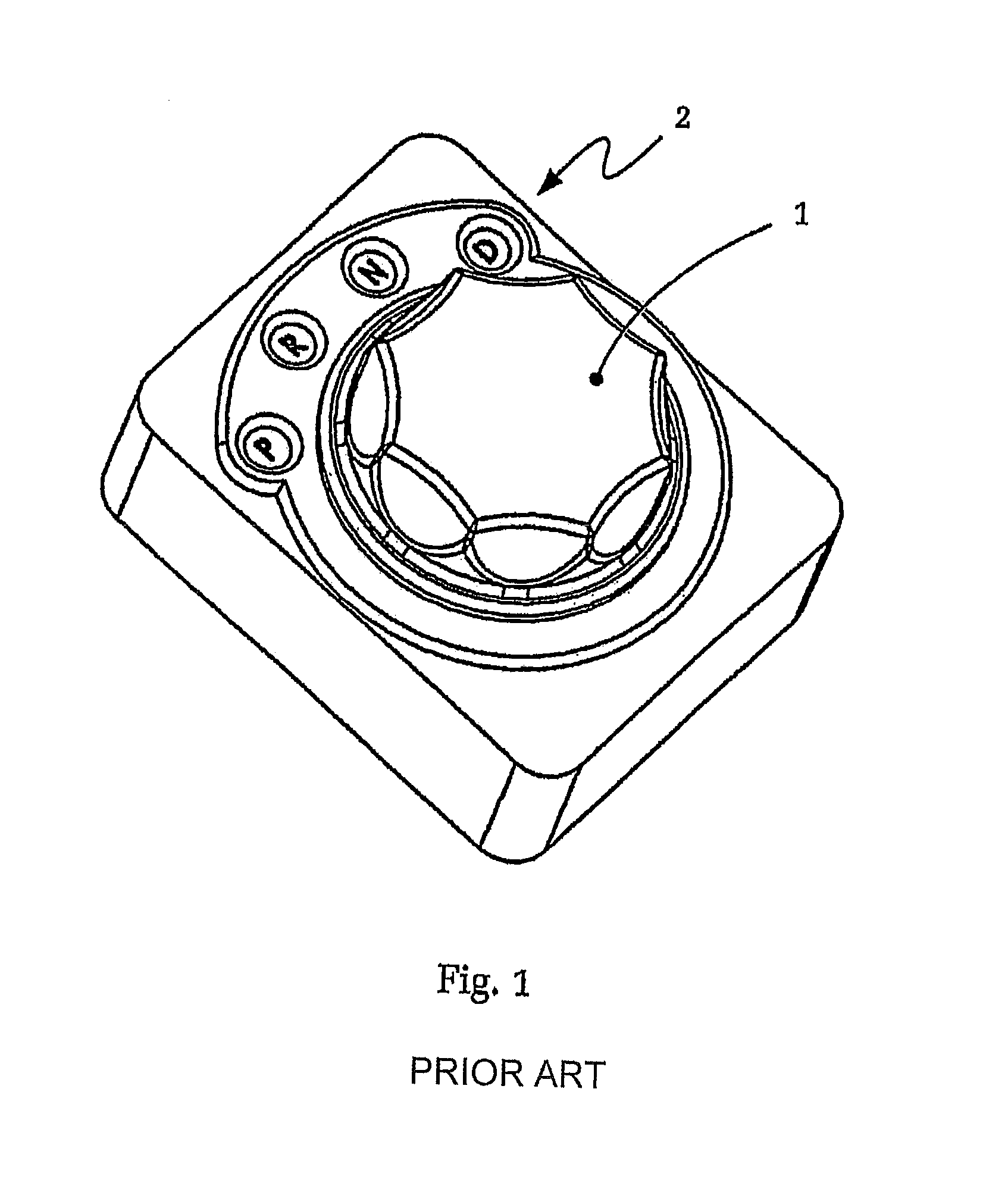
[0060]FIG. 1 is the schematic, isometric presentation of an actuating device for an actuating controlled automatic transmission of a motor vehicle. This operating device, for example mounted on the center console of the vehicle, essentially has a rotation symmetric rotary knob 1, without any pointer, as well as a gear display unit 2 for visualization of the engaged drive step. The rotary knob is configured, by itself, as an unlimited rotatable indifferent-multi stable gear selector part.

[0061]That implies that, in the first instance, no determined connection exists between the rotation angle position of the rotary knob 1 and the shift condition of the automatic transmission or the engage drive step of the transmission. However, the connection between the rotary angle position of the rotary knob 1 and the shift state in the automatic transmission is established, first of all, through the control electronic of the actuating device, whereby the gear display device 2 is triggered in a l...


PUM


Abstract

An actuating device for selection on shift steps of a gear changing transmission. The actuating device comprises a flexible gear selection device (1) with at least two drive step positions, a park lock position and an additional park lock-actuating device (4) for activation of the park lock. When the gear selector device (1) moves out of the park lock position, the gear selector device (1) becomes disengaged while movement of the gear selector device (1) from one of the drive step positions into the park lock position, or beyond the previous park lock position, does not engage the park lock. Engagement of the park lock is only achieved by actuating the additional park lock-actuating device (4). This improves the safety and provides intuitive shifting between the different drive step positions without the need to view the gear selector device. The unintended engagement of the park lock is precluded.

Description

[0001]This application is a National Stage completion of PCT / DE2008 / 050023 filed Aug. 6, 2008, which claims priority from German patent application serial no. 10 2007 037 707.1 filed Aug. 9, 2007.FIELD OF THE INVENTION[0002]The invention relates to an actuating device for selection of shift steps of a gear changing transmission, for example, an automatic transmission with a shift-by-wire operation.BACKGROUND OF THE INVENTION[0003]Gear changing transmissions for motor vehicles are usually controlled or shifted, respectively, by means of an actuating device within hand-reach of the driver. Regularly, the actuating devices, such as shift lever or selector lever, in these cases are applied and positioned between the front seats or on the center console of the motor vehicle, for instance.[0004]The constructive and ergonomic requirements for these actuating devices, for gear changing transmissions, are diverse. For instance, to suggest to the driver a realistic feeling of the transmission...

Claims


Application Information

Patent Timeline
Patent Type & Authority Patents(United States)
IPC IPC(8): B60K20/00F16H59/04
CPCB60K37/06F16H59/08B60K2350/102Y10T74/2003F16H2059/081Y10T74/2014F16H63/3458F16H63/3416F16H63/42F16H2063/423B60K2370/126
Inventor GIEFER, ANDREASMEYER, JORGRAKE, LUDGER
Owner ZF FRIEDRICHSHAFEN AG
Learn More