
Center airbag module for vehicle

a technology for airbag modules and vehicles, applied in the direction of vehicle components, pedestrian/occupant safety arrangements, vehicular safety arrangments, etc., can solve the problems of inability to minimize the movement of passengers towards the far side in an empty space above the console box, and increase the manufacturing cost and weight of the product, so as to minimize the movement of passengers

Active Publication Date: 2013-04-09
HYUNDAI MOTOR CO LTD
View PDF24 Cites 31 Cited by
  • Summary
  • Abstract
  • Description
  • Claims
  • Application Information

AI Technical Summary

Benefits of technology

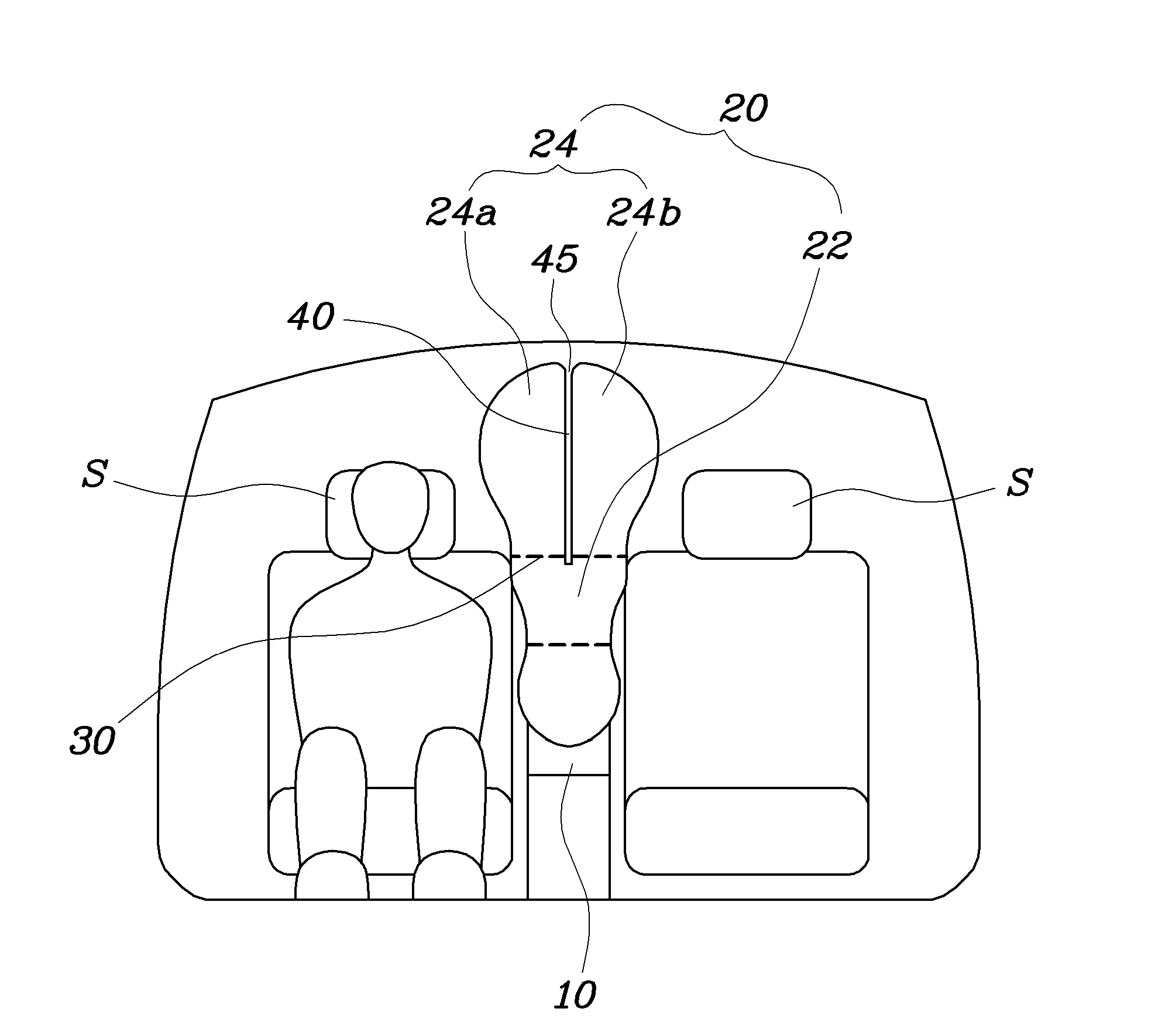
The present invention relates to a center airbag module for a vehicle that is designed to minimize the movement of a passenger towards a far side and the risk of injury in the event of a side collision. The module includes a lower chamber and two upper chambers that branch from the lower chamber. The center console, which is placed between two seats, has a curved surface and an airbag cushion that is designed to deploy in the event of a side collision. The airbag cushion has a lower chamber that supports the passenger's body and an upper chamber that protects the passenger's head. After deployment, the airbag cushion fits between the roof of the vehicle and the curved surface of the center console, providing support for a lateral movement of the passenger. Overall, this design helps to keep passengers safe and secure during a collision.

Problems solved by technology

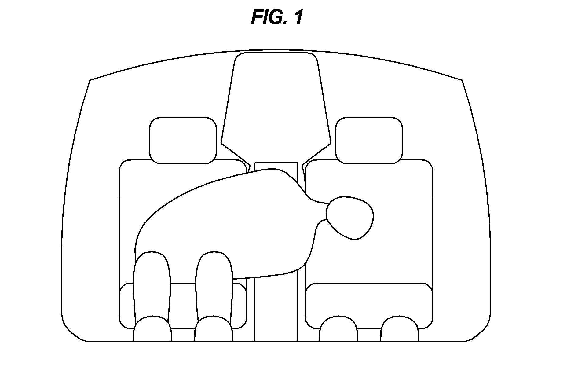
If the center airbag apparatus is not installed in a vehicle, a passenger may be moved towards the far side by the abrupt shock in the event of a side collision.
In this case, the passenger may collide with objects in the interior of the vehicle, or his or her head may collide with the head of a neighboring passenger, so that the passenger may be severely injured.
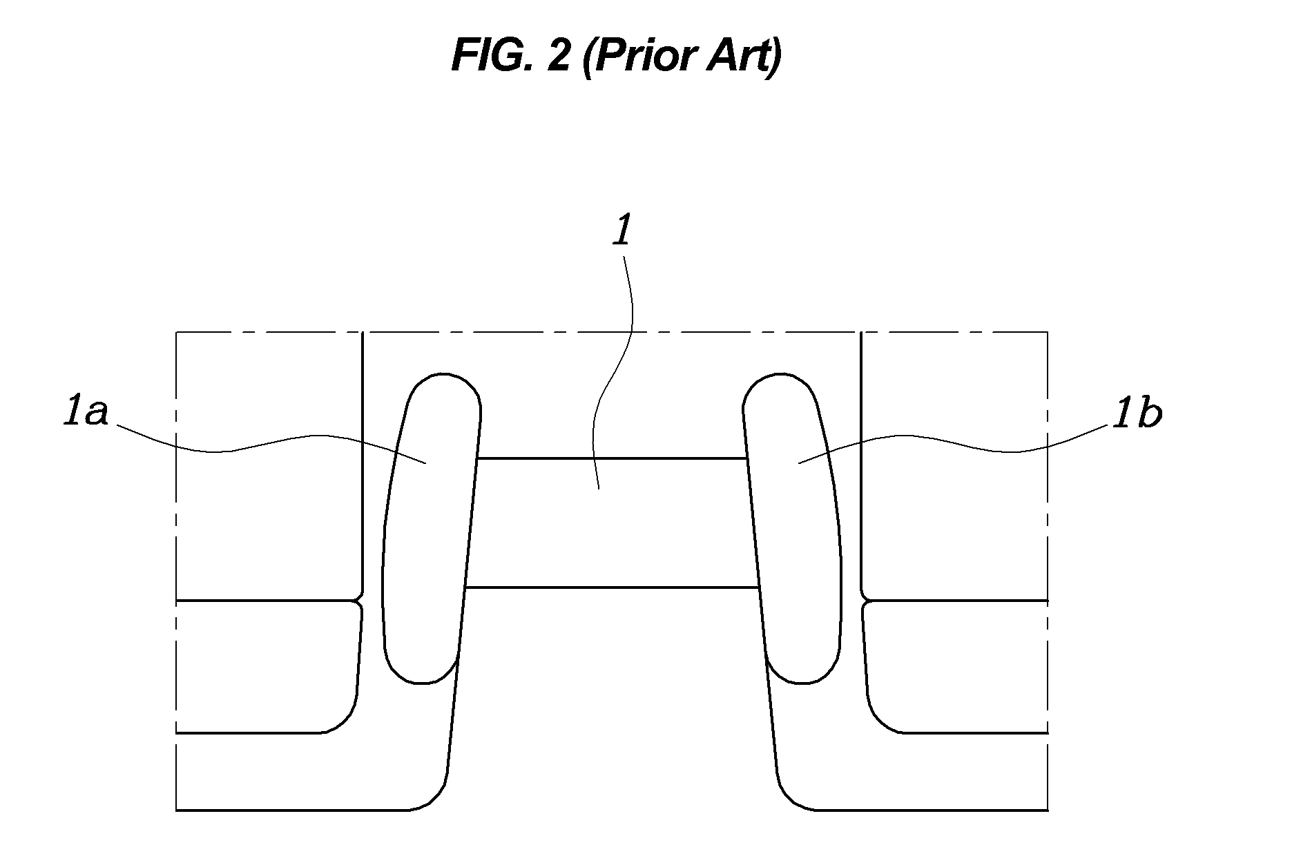
The center airbag apparatus is problematic in that it has two independent chambers 1a and 1b, so that its manufacturing cost and weight are increased.
Further, since the chambers 1a and 1b provided on the opposite sides of the console box 1 are deployed in the transverse direction of the vehicle, it is impossible to minimize the movement of a passenger towards the far side in an empty space above the console box 1.
The center airbag apparatus is problematic in that it has a single chamber 3 and the support force of the chamber 3 is too large, so that a passenger's head is subjected to a large reaction force that bends it towards an opposite side.

Method used


Image

  • Center airbag module for vehicle
  • Center airbag module for vehicle
  • Center airbag module for vehicle

Examples


Embodiment Construction

[0034]Reference will now be made in detail to various embodiments of the present invention(s), examples of which are illustrated in the accompanying drawings and described below. While the invention(s) will be described in conjunction with exemplary embodiments, it will be understood that present description is not intended to limit the invention(s) to those exemplary embodiments. On the contrary, the invention(s) is / are intended to cover not only the exemplary embodiments, but also various alternatives, modifications, equivalents and other embodiments, which may be included within the spirit and scope of the invention as defined by the appended claims.

[0035]Hereinafter, a center airbag module for a vehicle according to the exemplary embodiment of the present invention will be described with reference to the accompanying drawings.

[0036]As shown in FIG. 4, a center airbag module for a vehicle according to an exemplary embodiment of the present invention includes a center console 10 a...


PUM


Abstract

A center airbag module for a vehicle, may include a center console provided between a pair of seats, and an airbag cushion provided in the center console to be deployed in the event of a side collision, and having a lower chamber configured to support a body of a passenger, and an upper chamber including a left chamber and a right chamber which fluid-branch from an upper end of the lower chamber and configured to protect a head of the passenger.

Description

CROSS-REFERENCE TO RELATED APPLICATIONS[0001]The present application claims priority to Korean Patent Application No. 10-2010-0112641 filed on Nov. 12, 2010, the entire contents of which is incorporated herein for all purposes by this reference.BACKGROUND OF THE INVENTION[0002]1. Field of the Invention[0003]The present invention relates generally to center airbag modules for vehicles and, more particularly, to a center airbag module for a vehicle, which restrains the movement of a passenger towards a far side, when a vehicle collision occurs at the far side of the passenger, thus minimizing an injury to the passenger.[0004]2. Description of Related Art[0005]Generally, airbag systems for vehicles are a safety device that deploys an airbag cushion in the event of a vehicle collision to mitigate shocks and prevents a passenger from being thrown out of a vehicle body. The airbag systems are typically classified into a driver airbag (DAB) and a passenger airbag (PAB) for protecting passe...

Claims


Application Information

Patent Timeline
Patent Type & Authority Patents(United States)
IPC IPC(8): B60R21/214B60R21/231B60R21/233
CPCB60R21/23138B60R21/233B60R2021/23161B60R2021/23308
Inventor CHOI, JAE HOCHOI, HYEONG HO
Owner HYUNDAI MOTOR CO LTD
Learn More