
Methods and devices for reducing reflection-illuminated artifacts

a technology of reflection and artifacts, applied in the field of methods and devices for reducing reflection-illuminated artifacts, can solve problems such as reflection-illuminated artifacts, and achieve the effect of preventing or reducing the transmission of ligh

Active Publication Date: 2013-04-09
MAQUET CARDIOVASCULAR LLC
View PDF16 Cites 16 Cited by
  • Summary
  • Abstract
  • Description
  • Claims
  • Application Information

AI Technical Summary

Benefits of technology

The patent text describes a blocking member that can prevent or reduce the transmission of light. This blocking member can be opaque, translucent, or reflective. The technical effect of this invention is to provide a way to control the light transmission in a device, which can improve its performance and reliability.

Problems solved by technology

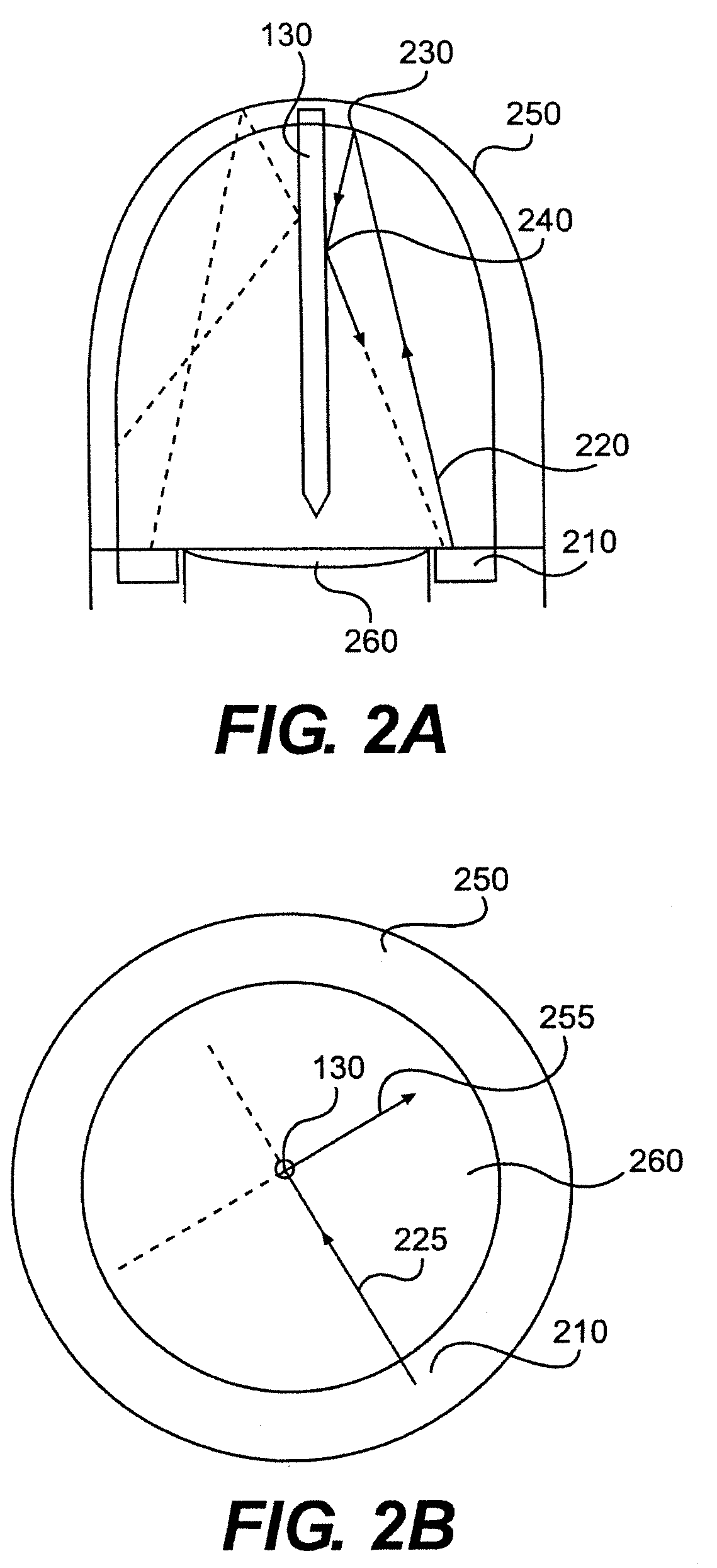
For example, light reflecting back into the detector can cause reflection-illuminated artifacts.

Method used


Image

  • Methods and devices for reducing reflection-illuminated artifacts
  • Methods and devices for reducing reflection-illuminated artifacts
  • Methods and devices for reducing reflection-illuminated artifacts

Examples


Embodiment Construction

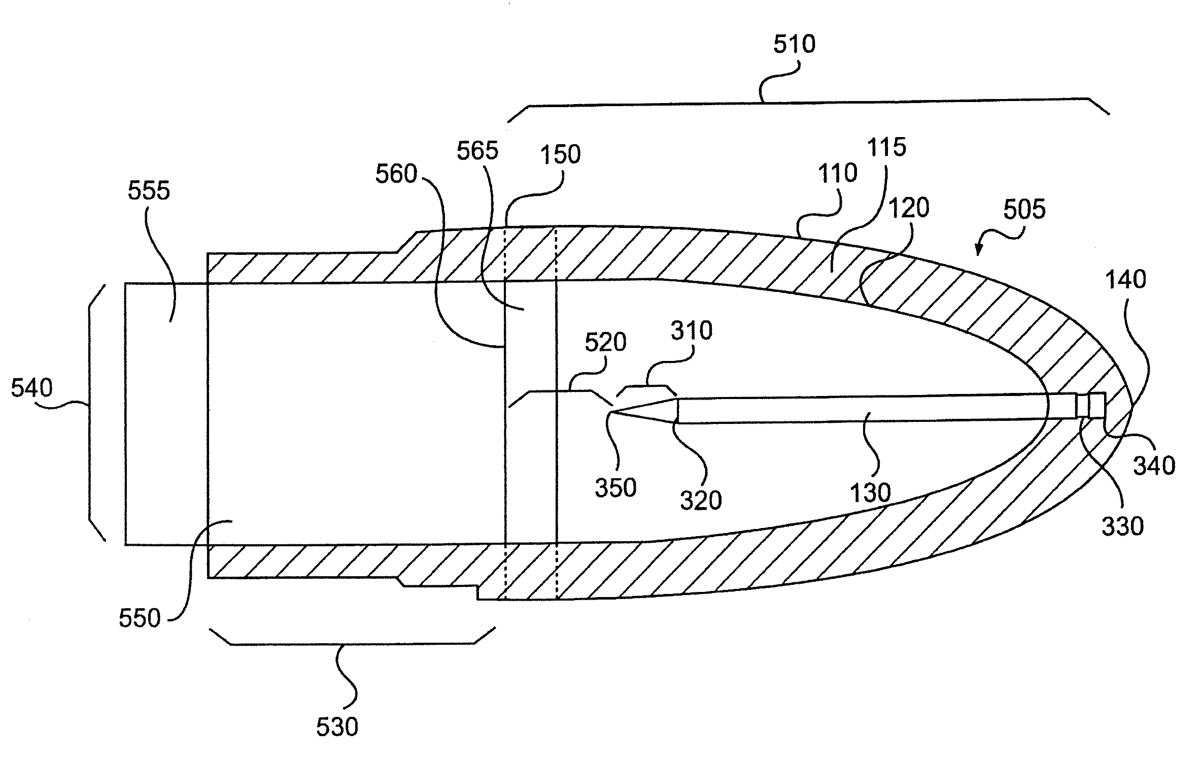
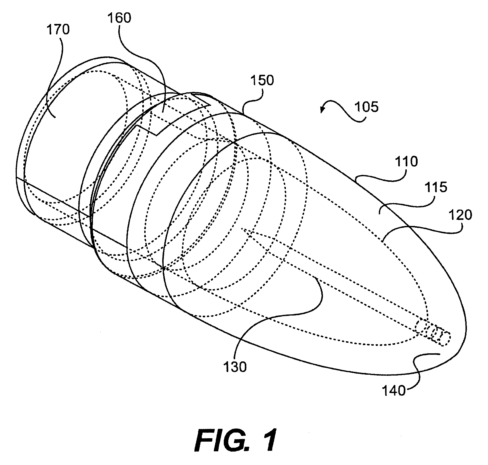
[0032]Reference will now be made in detail to the present exemplary embodiments, examples of which are illustrated in the accompanying drawings. Wherever possible, the same reference numbers will be used throughout the drawings to refer to the same or like parts.

[0033]It is to be understood that both the foregoing background description and the following detailed description are exemplary and explanatory only and are not restrictive. The following embodiments should not be limited to a particular surgery, diagnosis, or procedure type. Similarly, although the user of an embodiment can be referred to as a surgeon, a surgeon is only one type of user capable of using the embodiments herein.

[0034]For the purposes of this disclosure, an endoscope can represent any type of imaging device used in a medical procedure. Such endoscopes can generally include an image receiving element, herein referred to as a detector. The detector can include a lens, opening, and / or transparent shield through ...


PUM


Abstract

The present disclosure is generally directed towards methods and devices for reducing or eliminating reflection-illuminated artifacts. The methods and devices in several embodiments can include providing a transparent lens cover with a blocking member for reflecting or absorbing internally-reflected light. The lens cover can be attached at the distal end of an endoscope, cannula, and / or lumen in some embodiments. Alternatively, the lens cover can be a permanent part of the endoscope, lumen, and / or cannula.

Description

CROSS-REFERENCE TO RELATED APPLICATIONS[0001]This application claims priority to U.S. Provisional Application Ser. No.: 60 / 907,150, entitled “Methods and Devices For Reducing Reflected-Illuminated Artifacts,” filed Mar. 22, 2007, the contents of which are incorporated herein by reference.BACKGROUND OF THE INVENTION[0002]The ability to view internal anatomy has lead to significant advances in surgical capability and diagnosis. In particular, the number of procedures that can be performed in a minimally-invasive manner has increased, while such procedures have, in general, improved patient outcomes and reduced recovery time.[0003]To provide visibility, the distal end of an endoscope can be inserted into the patient through a small hole. Usually, the endoscope is an elongated device that includes a lens at the distal end, and an eyepiece or camera at the proximal end. In addition, a working channel can allow for the delivery of surgical instruments, the collection of samples, and / or im...

Claims


Application Information

Patent Timeline
Patent Type & Authority Patents(United States)
IPC IPC(8): A61B1/06G02B6/06
CPCA61B1/00096A61B1/00142A61B1/00101A61B1/00137
Inventor KENDALE, AMARTAMKIN, JOHNPOST, ETHAN
Owner MAQUET CARDIOVASCULAR LLC
Learn More