Long nose manipulatable catheter

a catheter and long nose technology, applied in balloon catheters, blood vessels, surgery, etc., can solve the problems of inadvertent embolism, difficult to reach the target site of malady, and the risk of embolic coils being placed the same way

Inactive Publication Date: 2013-04-09
VASCULAR FX +2
View PDF41 Cites 2 Cited by
  • Summary
  • Abstract
  • Description
  • Claims
  • Application Information

AI Technical Summary

Benefits of technology

[0018]The manipulatable or flexible joint region is generally located at the distal end of the catheter body and is configured to bend when manipulated by the push-pull wire. The bending portion itself may be varied to extend to where the braid terminates, or it may be extended to the bending portion to encompass a portion of the braid. By varying the length of the flexible joint region, the amount of curvature and flexure of the joint region can be controlled. For instance, a joint region having a relatively shortened length between the distal end of the joint region and the terminal end of the braid may allow for a reduced degree of flexure relative to a neutral position of the catheter. In comparison, a lengthened joint region extending to a more proximally located terminal end may allow for a relatively greater degree of flexure. Accordingly, the degree of flexure may be controlled in part by the length of the flexible joint region. Thus, the flexible region may be flexed up to 90° relative to the longitudinal axis of the catheter assembly and in some cases, the flexible region may be flexed up to 180° relative to the longitudinal axis depending upon the length of the flexible joint region. To further facilitate bending of the catheter, additional members such as coils may be incorporated into the device, for instance in the transitional region, to aid in further controlling the bending of the joint region.
[0026]A coil is also preferably disposed around the smaller diameter distal portion of the push-pull wire, which has the effect of distributing stress along the smaller diameter portion of the push-pull wire to prevent buckling of the smaller diameter portion of the push-pull wire, so that the tip of the push-pull wire does not deflect and rupture the catheter body. A control is also provided in communication with a proximal end of the push-pull wire for manipulating the flexible joint region.

Problems solved by technology

Often the target site of the malady is difficult to reach.
Inadvertent embolism due to an inability to contain the fluid agent within the aneurysm is one risk which might occur when using fluid embolic agents.
Some embolic coils are subject to the same placement risks as that of fluid embolic agents in that it is difficult to contain the occlusive coil within the open space of the aneurysm.
However, none of the above-mentioned devices discloses an intravascular device having a small diameter, highly flexible construction which permits movement along a small-diameter, tortuous vessel path, and having a flexible method of placement to ensure accuracy, as disclosed herein.

Method used


Image

  • Long nose manipulatable catheter
  • Long nose manipulatable catheter
  • Long nose manipulatable catheter

Examples


Embodiment Construction

[0055]While preferred embodiments of the present invention have been shown and described herein, it will be obvious to those skilled in the art that such embodiments are provided by way of example only. Numerous variations, changes, and substitutions will now occur to those skilled in the art without departing from the invention. It should be understood that various alternatives to the embodiments of the invention described herein may be employed in practicing the invention. It is intended that the following claims define the scope of the invention and that methods and structures within the scope of these claims and their equivalents be covered thereby.

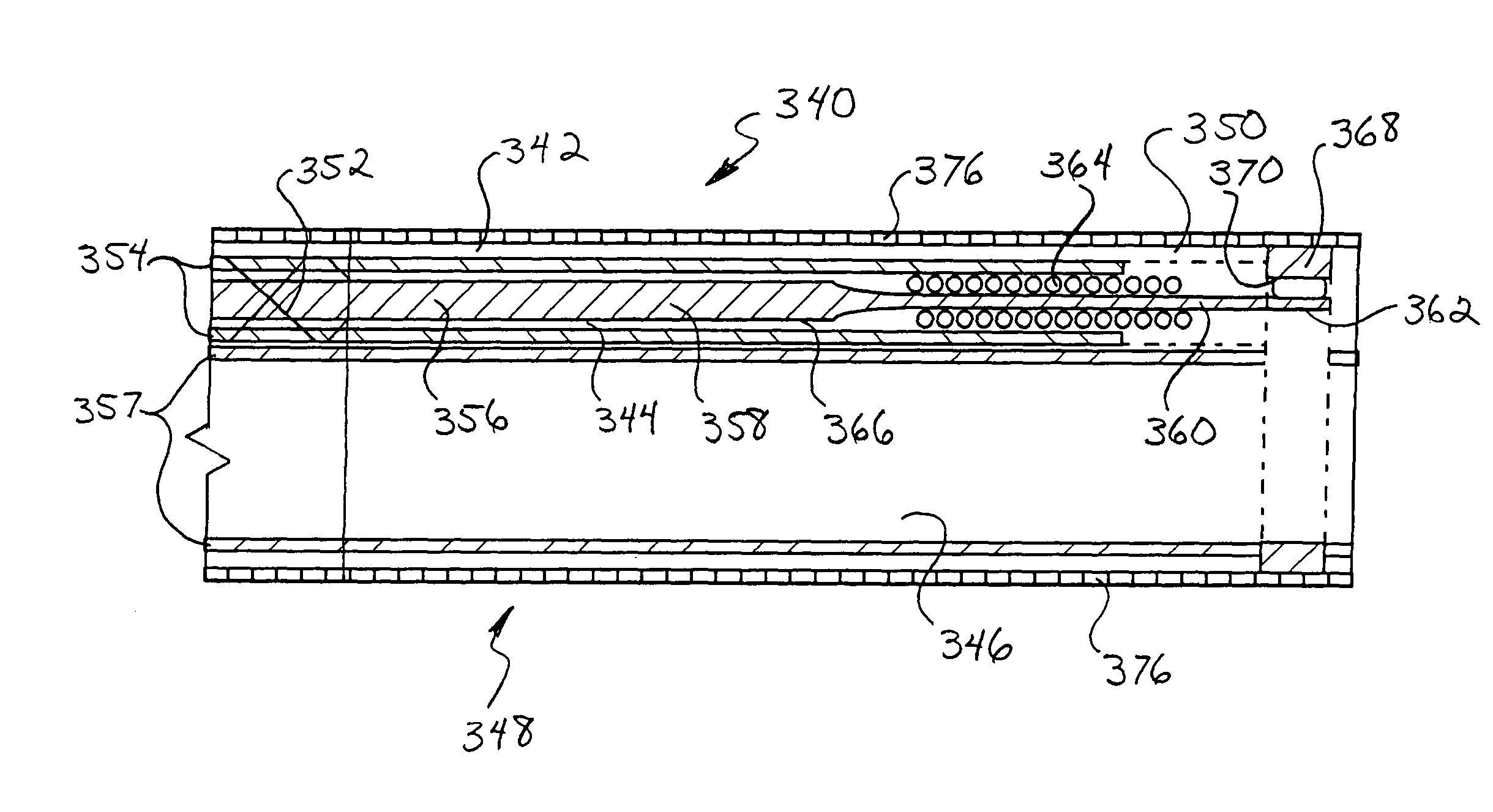
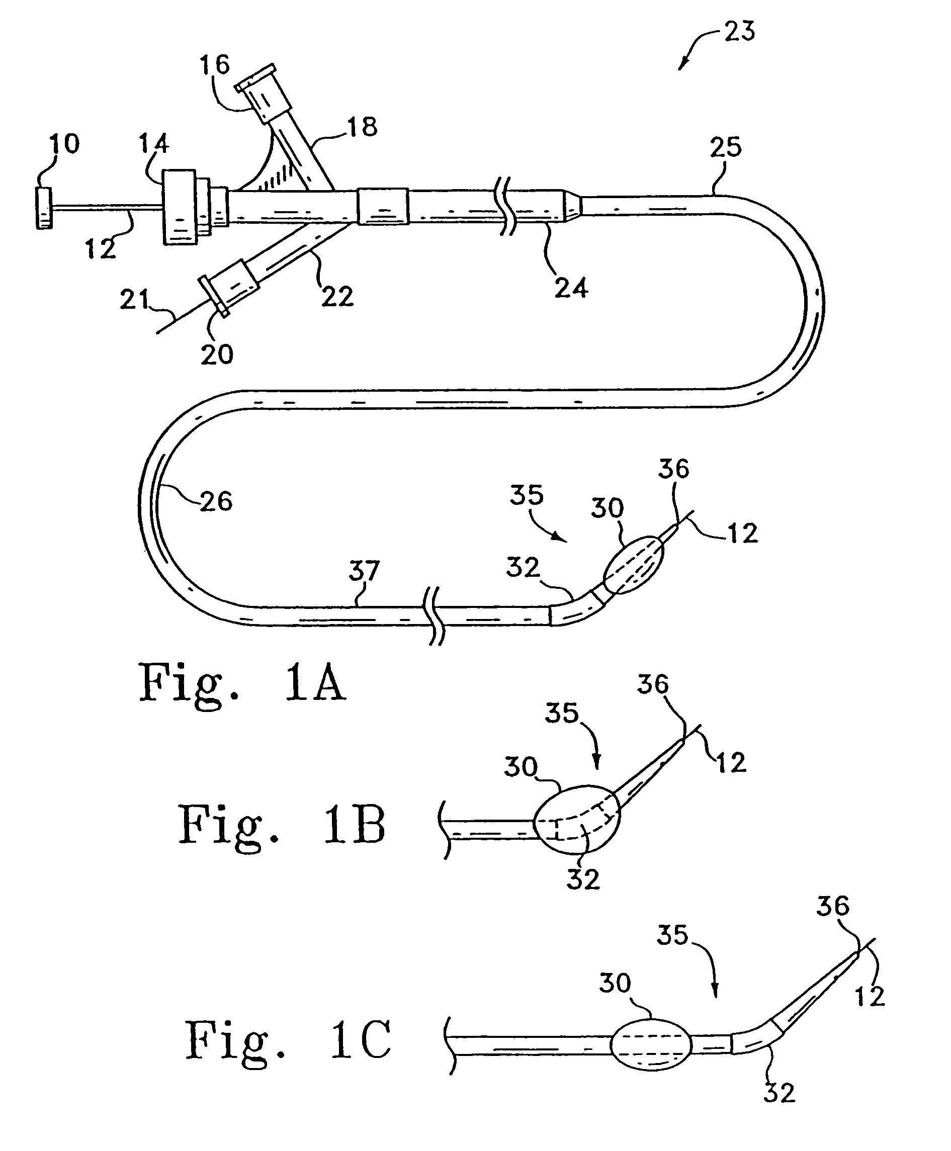
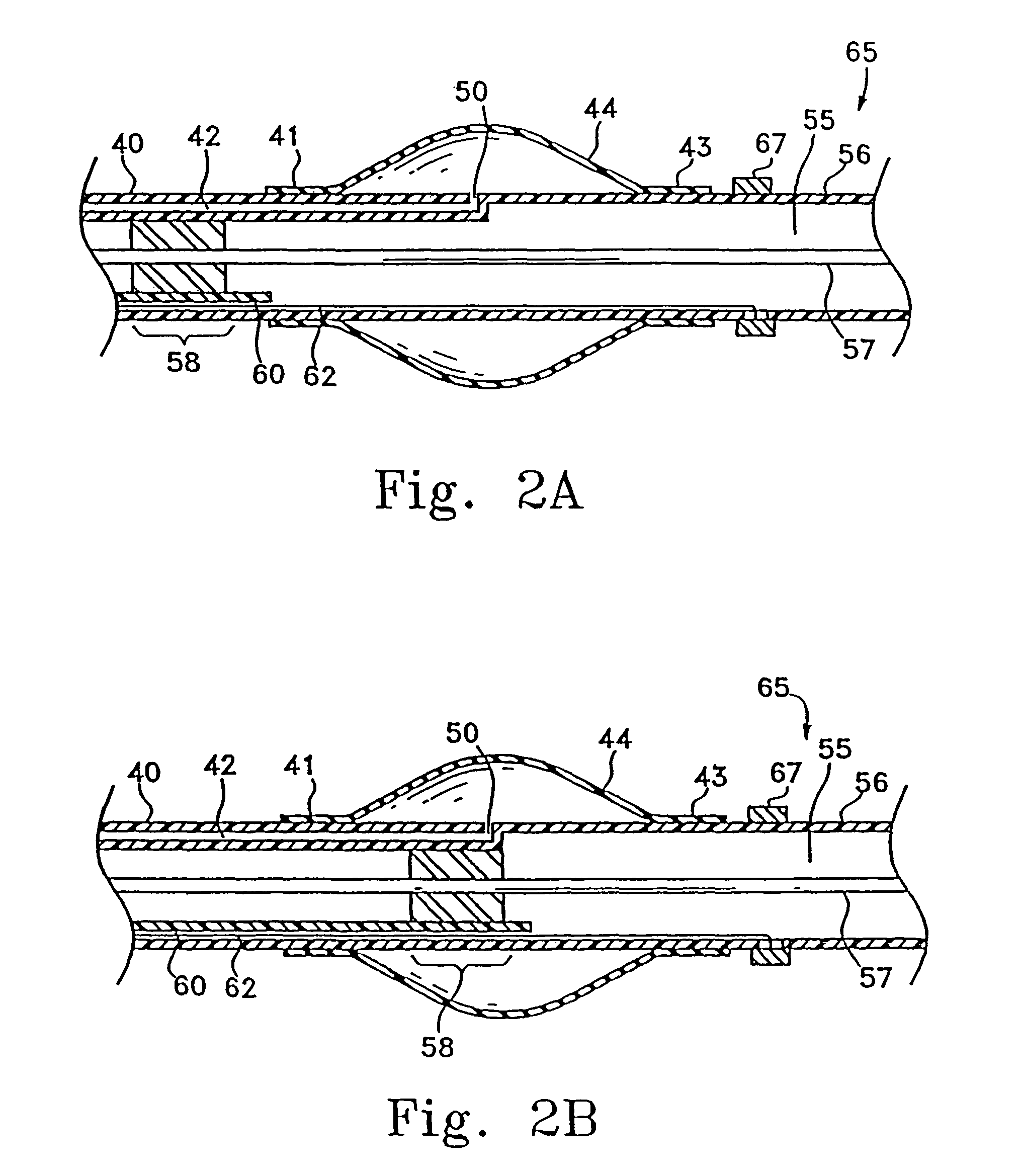
[0056]This invention involves a multi-lumen catheter for the delivery of vaso-occlusive materials or implants. The device may optionally include a balloon member. The device is shown in detail in the figures wherein like numerals indicate like elements. The catheter preferably includes a shapeable, flexible distal section which may be...


PUM


Abstract

The long nose manipulatable catheter includes a main lumen, a wire lumen with a push-pull wire therethrough, and a flexible joint region. The catheter section includes a control including a handle and a wire control member engaging the push-pull wire for manipulating the flexible joint region. The push-pull wire may be tapered, having a proximal portion of a first diameter and a smaller diameter distal portion. A coil may be placed around the smaller diameter to prevent buckling of the smaller diameter portion. A strapping coil may also disposed around the outside of the catheter, and an outer covering may be disposed around the strapping coil. An outer covering of a mesh may also be disposed around the distal tip of the catheter.

Description

CROSS-REFERENCES TO RELATED APPLICATIONS[0001]This application is a continuation-in-part application of Ser. No. 10 / 678,008, filed Oct. 1, 2003 now U.S.Pat.No. 7,591,813, which is incorporated herein by reference in its entirety and to which application we claim priority under 35 U.S.C. §120.FIELD OF THE INVENTION[0002]The invention is generally in the field of intravascular devices. More particularly, it relates to intravascular catheters having a flexible and manipulatable hinge or joint region. The delivery lumen may be also used for placement of occlusive materials, e.g., in an aneurysm.BACKGROUND OF THE INVENTION[0003]Endovascular therapy has been used to treat different conditions, such treatments including control of internal bleeding, occlusion of blood supply to tumors, and occlusion of aneurysm. Often the target site of the malady is difficult to reach. Because of their ability to access remote regions of the human body and deliver diagnostic or therapeutic agents, cathete...

Claims


Application Information

Patent Timeline
Patent Type & Authority Patents(United States)
IPC IPC(8): A61M31/00A61M37/00A61M25/00A61F2/06A61M25/01A61M25/10
CPCA61M25/008A61M25/0136A61M25/0147A61M25/0068A61M25/10A61M2025/015A61M2025/1079A61M2025/1093
Inventor LEVINE, MARC-ALANHEBERT, STEPHENBRETON, THOMAS G.WATSON, DAVID A.
Owner VASCULAR FX
Why Eureka
Try Eureka