
Display apparatus

a technology of display apparatus and contact surface, which is applied in the field of display apparatus, can solve the problems of large distance between the display surface and the contact surface of the pen, attenuation of the electromagnetic field, and worsening the sensitivity of position detection, so as to achieve the effect of not easily broken and impairing the luminan

Inactive Publication Date: 2013-04-09
CANON KK
View PDF21 Cites 2 Cited by
  • Summary
  • Abstract
  • Description
  • Claims
  • Application Information

AI Technical Summary

Benefits of technology

[0020]An object of the present invention is to provide a display apparatus capable of performing high-accuracy coordinate position detection by using a display including, as a substrate material, a thin metal plate which is not readily broken and is electroconductive.
[0021]Another object of the present invention is to provide such a display apparatus without providing inconformity to a user and impairing a luminance.

Problems solved by technology

For this reason, there has arisen such a problem that the electromagnetic field is attenuated to worsen a sensitivity for position detection.
For this reason, an actual distance between the display surface and the pen contact surface becomes large, whereby parallax is caused.
As a result, a user has such a sense that it is difficult to write or there is conformity, considerably different from the case where writing is performed in ordinary paper.
Further, light passes through at least a thickness corresponding to two layers of transparent electrode, so that there also arises such a problem that a resultant light amount is decreased to approximately 90% compared with the case where a sensor is not provided at the surface of the display apparatus it varies depending upon the thickness.

Method used


Image

  • Display apparatus
  • Display apparatus
  • Display apparatus

Examples


example 1

[0103]In this example, the display apparatus according to First Embodiment of the present invention is prepared in the following manner.

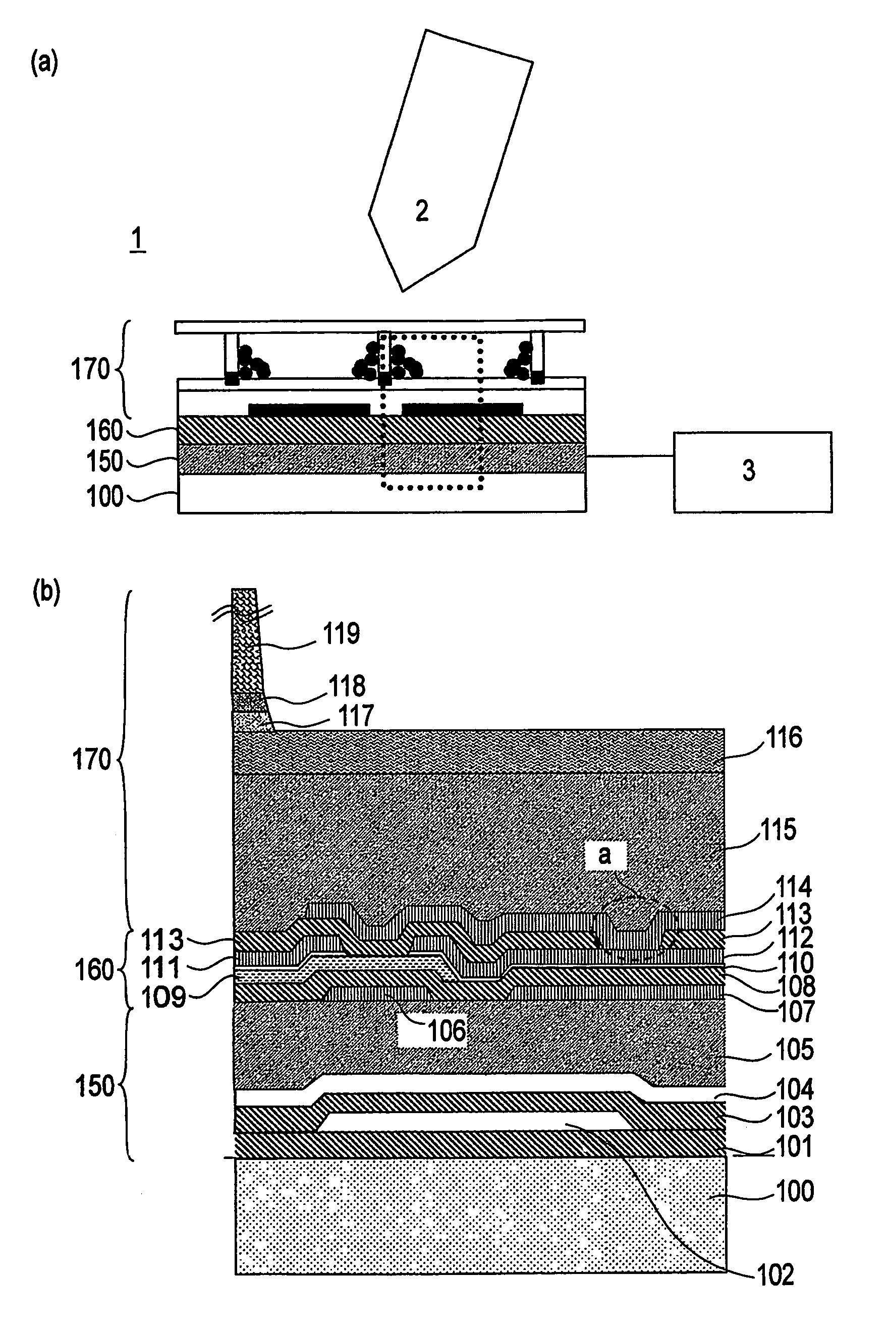
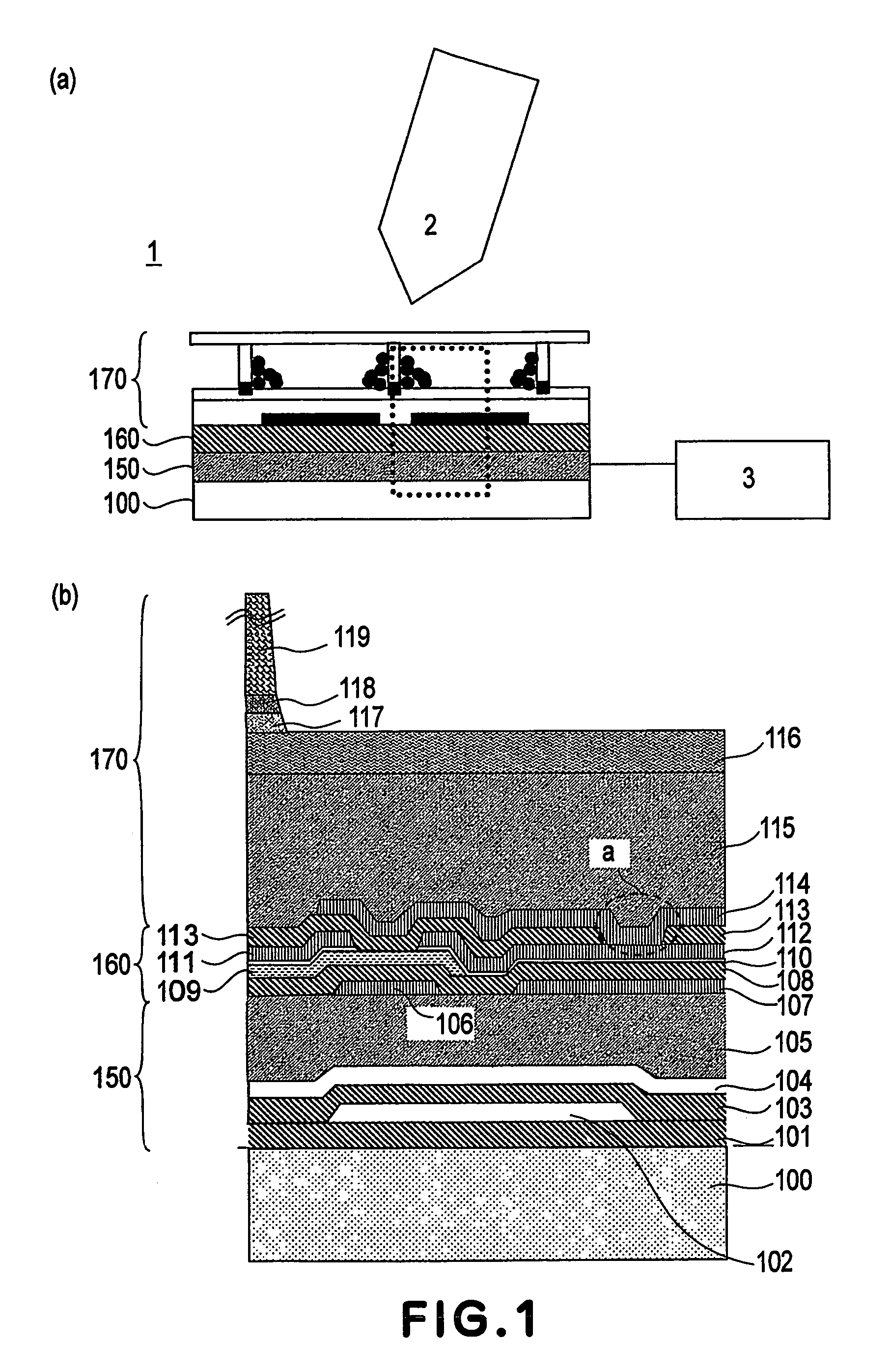
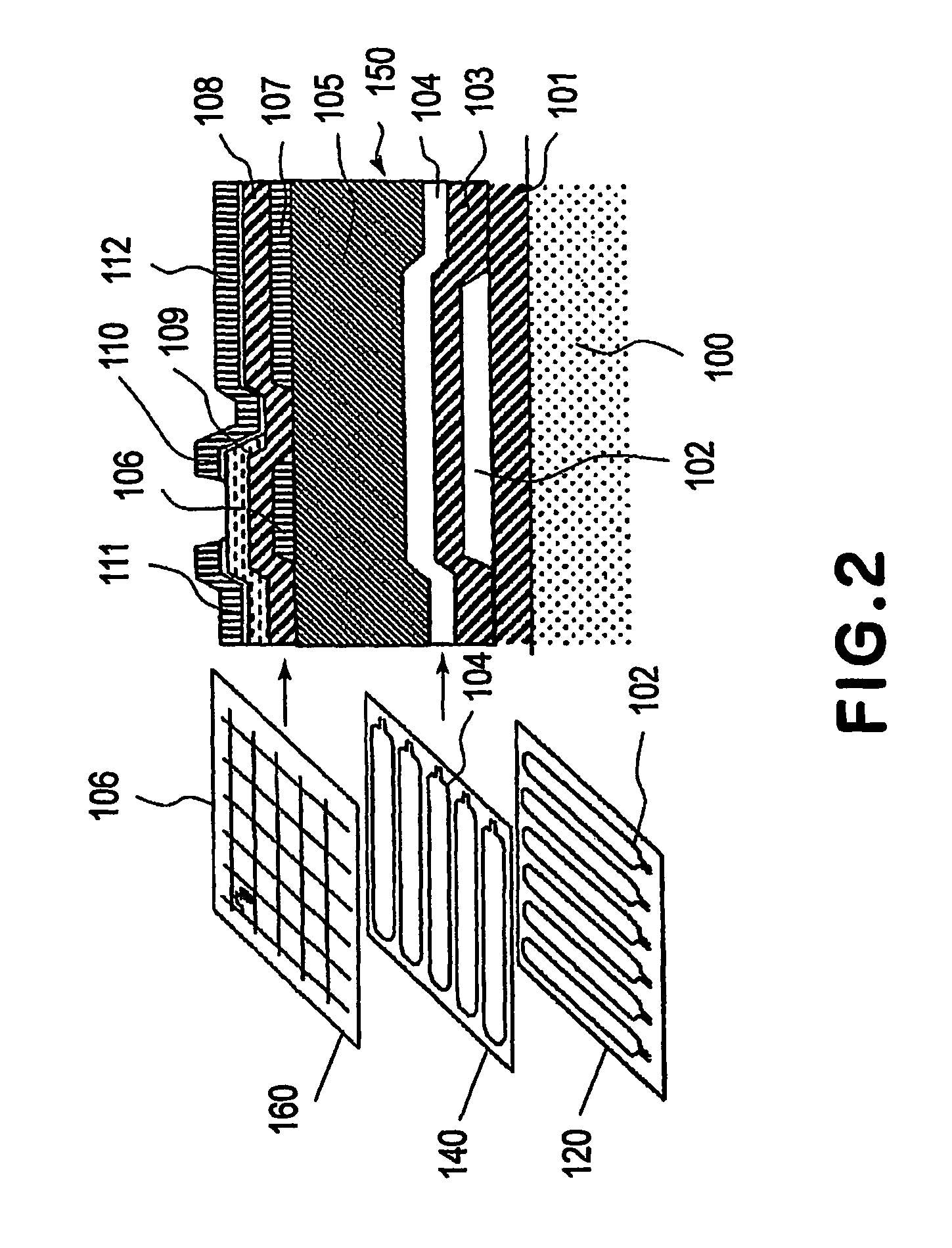
[0104]A substrate 100 is a thin electroconductive SUS foil or plate. An insulating film 101 disposed on the substrate 100 is formed of an insulating material such as SiN or a resin material. As wiring (metal coils) 102 and 104, a wiring material of A1 which exhibits a low electric resistivity is used but in the case where there is a subsequent step including a production process performed at a temperature that exceeds a melting temperature of A1, a metal material such as Cr, Ta or Al—Nd is used instead of Al. Such a metal material is vapor-deposited on the insulating film by sputtering and thereon, a photoresist is applied and subjected to selective exposure and development, followed by etching of the metal film to form a loop-like wiring portion. As a TFT 109, a thin film of an amorphous semiconductor is used.

[0105]More specifically, the display ap...

example 2

[0127]In this example, the display apparatus of Second Embodiment of the present invention is prepared in the following manner.

[0128]First, the structure of display apparatus will be described with reference to FIG. 6.

[0129]In this example, a 100 μm-thick SUS sheet A1 in which a multiplicity of through holes 4 are formed with an opening width of 20 μm, is used. Further, as an insulating liquid 15, it is possible to use a liquid principally comprising a paraffin-based hydrocarbon solvent. As charged electrophoretic particles 16, it is possible to use black particles of carbon black-containing polystyrene resin.

[0130]The SUS substrate A1 and the through holes 4 are coated and filled with an acrylic resin layer (thickness: 2 μm) for electrical insulation and smoothness. Further, it is also possible to use an SiN epoxy-based resin film instead of the acrylic resin. In the latter case, however, it is difficult to realize a film thickness of not less than 1 μm in CVD used when the SiN fil...


PUM


Abstract

A display apparatus includes a substrate having a metal layer, a display device disposed on the substrate, with the display device including a display portion and a driving portion, and a sensor portion for detecting a coordinate using electromagnetic induction. The sensor portion is arranged on an opposite side of the substrate from where the display device is disposed, and the metal layer of the substrate has an electromagnetic wave transmissive structure.

Description

TECHNICAL FIELD[0001]The present invention relates to a display apparatus, particularly a display apparatus capable of performing pen input.BACKGROUND ART[0002]With development of information equipment, the needs for low-powder and thin display apparatuses have grown, so that extensive study and development have been made on display apparatus fitted to these needs.[0003]Particularly, such a display apparatus if frequently used outdoors as a wearable PC (personal computer), an electronic notepad, etc., so that it is desirable that the display apparatus is of power and space saving type. For this reason, e.g., such apparatuses in which a display function of a thin display such as a liquid crystal display and a coordinate input process are integrated and a user can directly input information (data) to be displayed on the display by a pressing operation with a pen or finger have been commercialized.[0004]In these equipments, the user operates the equipments by designating a position wit...

Claims


Application Information

Patent Timeline
Patent Type & Authority Patents(United States)
IPC IPC(8): G09G3/36G06F3/041G06F3/046G06F3/0488G09F9/37
CPCG06F3/0412G06F3/046G06F3/0488
Inventor YOSHINAGA, HIDEKIMORI, HIDEOOKAMOTO, HIDEAKI
Owner CANON KK
Learn More