Flat tubularlamp

a technology of tubular lamps and tubes, applied in the field of flat tubes, can solve the problems of shortcoming of energy wastage, low luminous efficiency, environmental pollution, etc., and achieve the effects of reducing energy consumption, long-lasting and stable usage time span

Inactive Publication Date: 2013-04-16
ENLIGHT
View PDF2 Cites 4 Cited by
  • Summary
  • Abstract
  • Description
  • Claims
  • Application Information

AI Technical Summary

Benefits of technology

[0010]Per aforementioned, the flat fluorescent lamp provided by the embodiments of the present invention, has structure that can achieve the effect of becoming thinner, and can be connected to traditional lamp sockets through couple head, thereby achieve the effects of reduce energy consumption, possess long lasting and stable usage time span, and provides uniform and soft lighting.

Problems solved by technology

Generally, because a traditional fluorescent lamp (such as conventional T8 or T9 type fluorescent lamps) lights up inductively, therefore there are common short-comings of energy wastage, low luminous efficiency, and environmental pollution, which does not fit with modern trend of energy conservation.
The aforementioned T8 or T9 fluorescent tube 1a is currently the type of light tube used in a majority of family and offices, and is the traditional fluorescent light; however this type of fluorescent light uses a great amount of electricity and has a low luminous efficiency, which does not fit with modern requirement of environmental conservatism.

Method used


Image

  • Flat tubularlamp
  • Flat tubularlamp
  • Flat tubularlamp

Examples


first embodiment

[0023][The First Embodiment]

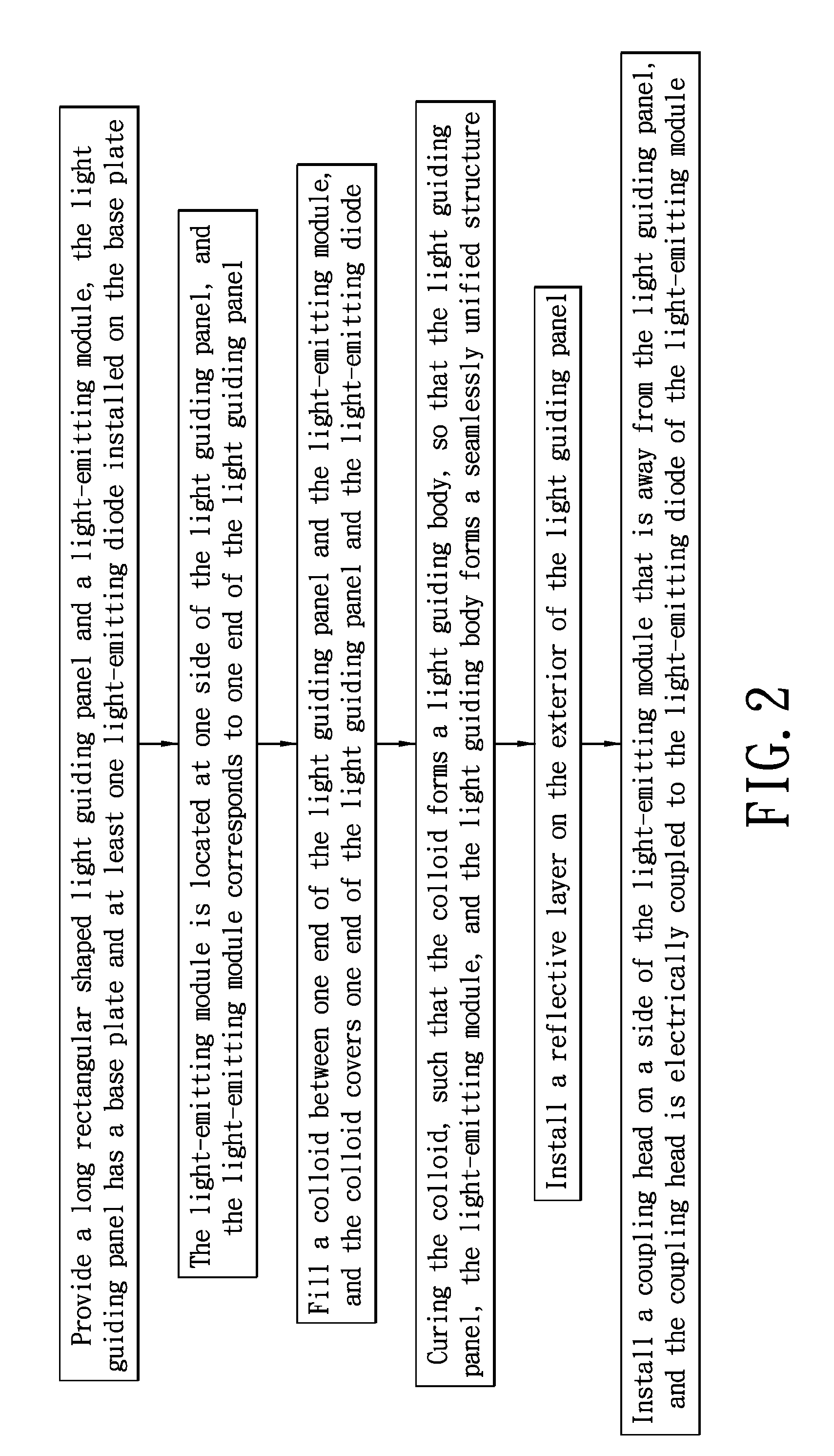
[0024]Reference FIGS. 2 to 7, which shows the first embodiment of the present invention; wherein FIG. 2 shows manufacturing method flow chart diagram of the present invention, FIGS. 3 to 7 shows perspective diagram of the present invention.

[0025]Refer to FIG. 2 while cross referencing FIGS. 3 to 7, the present invention shows a flat fluorescent lamp manufacturing method, the steps include:

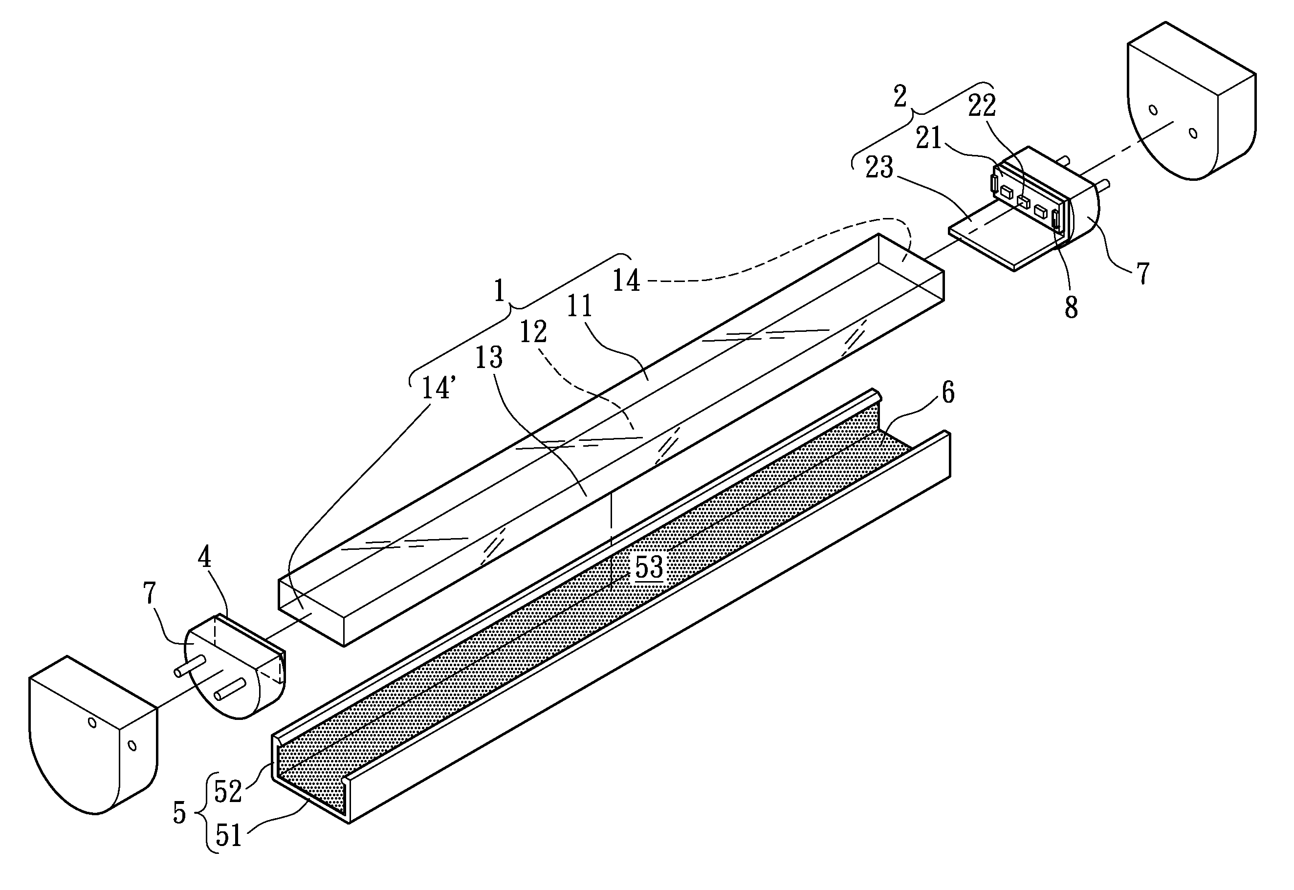
[0026]As show by FIG. 3, provide a long rectangular shaped light guiding panel 1 and a light-emitting module 2. The light guiding panel 1 has a corresponding light-emitting surface 11 and light-reflecting surface 12, and two long lateral surfaces 13 and two end surfaces 14, 14′ that connects with the edge of the light-emitting surface 11 and light-reflecting surface 12. The light-emitting module 2 has a base plate 21 and at least one light-emitting diode 22 installed on the base plate 21; wherein the base plate 21 is an aluminum substrate with formed circuit, the light-e...

second embodiment

[0044][The Second Embodiment]

[0045]Reference FIG. 8 to FIG. 10, which shows the second embodiment of the present invention; wherein FIG. 8 shows flow chart diagram of the present invention which differs from the first embodiment, FIGS. 9 and 10 shows perspective diagram of the present invention.

[0046]The present embodiment mainly connects another light-emitting module 2′ (also known as the second light-emitting module 2′) at another end surface 14′ of the light guiding panel 1 of the first embodiment, thereby replacing the end panel 4, and the another surface 14′ of the light guiding panel 1 does not install a reflective layer 6. The connecting steps for the light-emitting module 2′ on another end surface 14′ of the light guiding panel 1 is essentially the same as how the light-emitting module 2 connects with the end surface 14 of the light guiding panel 1 from the first embodiment.

[0047]Refer to FIG. 8 while cross referencing FIGS. 9 and 10, the difference in steps between the pres...

third embodiment

[0057][The Third Embodiment]

[0058]Reference FIGS. 3 and 9, which shows the third embodiment of the present invention; the present embodiment differs from the first and second, in the present embodiment, between the end surface 14 of the light guiding panel 1 and the base plate 21 of the light-emitting module 2 is installed with at least one stops 8, so as to prevent compression between the end surface 14 of the light guiding panel 1 and the base plate 21 of the light-emitting module 2, which could may damage light-emitting diode 22. Additionally, at least one stops 8 can be installed between the another end surface 14′ of the light guiding panel 1 and the base plate 21′ of the light-emitting module 2′.

[0059]Furthermore, for the present embodiment, the stops 8, 8′ on the two ends of the light guiding panel 1 is numbered in two, but in actual application the number of stops is not limited thereby.

[0060][The Effects of the Embodiments]

[0061]According to the embodiments of the present i...


PUM


Abstract

A flat fluorescent lamp which includes: a long rectangular shaped light guiding panel, a light-emitting module, a light guiding body, a reflective layer, and at least one light-emitting diode. The light guiding body seamlessly connects between an end surface of the light guiding panel and the light-emitting module. The reflective layer is located exterior of the light guiding panel. A Coupling head is installed on the side of the light-emitting module that is away from the light guiding panel, and the coupling head is connected to the light-emitting module. Thereby, an energy efficient fluorescent lamp that can be thinner and installed on general lamp socket is provided.

Description

BACKGROUND OF THE INVENTION[0001]1. Field of the Invention[0002]The present invention relates to a flat tubular lamp; in particular, to a low profile flat tubular lamp having backward compatible coupling heads adaptable onto existing lamp seats.[0003]2. Description of Related Art[0004]Generally, because a traditional fluorescent lamp (such as conventional T8 or T9 type fluorescent lamps) lights up inductively, therefore there are common short-comings of energy wastage, low luminous efficiency, and environmental pollution, which does not fit with modern trend of energy conservation.[0005]As show by FIG. 1, a prior art structure of fluorescent lamp, which includes lamp socket 1a and fluorescent tube 2a, the lamp socket 1a is installed on an indoor ceiling or hang freely below a ceiling; the fluorescent tube is of T8 or T9 specification, and using T8 as a 40 W fluorescent tube for example, the length is 1198 mm, the tube diameter is 26 mm, and its 2 ends are coupled with the lamp socke...

Claims


Application Information

Patent Timeline
Patent Type & Authority Patents(United States)
IPC IPC(8): F21V33/00
CPCF21K9/17G02B6/0023G02B6/0028G02B6/0073G02B6/0055G02B6/001F21V2200/20G02B6/0068G02B6/0088F21K9/27F21V29/70F21K9/61F21Y2115/10
Inventor LIAO, CHIH-MINGHUANG, JIH-SHENGCHUANG, CHI-FU
Owner ENLIGHT
Why Eureka
Try Eureka