
Fixed focal length lens

a fixed focal length, lens technology, applied in the field of lenses, can solve the problems of increased design difficulty increased cost, increased size of the projection lens, etc., and achieve the effect of good optical imaging quality

Active Publication Date: 2013-04-16
YOUNG OPTICS
View PDF20 Cites 3 Cited by
  • Summary
  • Abstract
  • Description
  • Claims
  • Application Information

AI Technical Summary

Benefits of technology

The lens configuration achieves a balance of high image quality, low distortion aberration, and a large field of view with a small telecentric angle, while reducing the overall size and cost by using fewer lenses and incorporating aspheric and spherical lenses strategically.

Problems solved by technology

Design of a projection lens is a challenge for an optical lens designer.
The above design requirements are impeded by each other, so that a design difficulty of the projection lens is increased.
Moreover, to achieve the advantages of high imaging quality, low distortion aberration, high resolution, high contrast, and uniform image illumination, aspheric lenses are generally used though application of the glass aspheric lenses may increase a cost, so that the cost of the projection lens may not be reduced.
If spherical lenses are used for a projection lens merely, the number of the lenses used by the projection lens may be over and above 9, so that the size of the projection lens is increased, and the cost of the projection lens may not be effectively reduced.
A back focal length of the front lens group is longer, and thus a length of the whole lens set is longer as well, which is hard to miniaturize the lens set.
Since the plastic aspheric lens is close to the reduced side, it is difficult to assemble.
In other words, a focusing mode of the lens is not an internal focusing type, and an emitting light is liable to be interfered with other mechanical members, so that a shade angle problem of an imaged picture occurs.
In addition, since the number of the glass lenses used by the lens set is 6, a lightweight of the lens may not be achieved, and a cost of the lens set may not be reduced.
The number of the glass lenses of the lens set is relatively more, so that a lightweight of the lens set may not be achieved, and a cost of the lens may not be reduced.

Method used


Image

  • Fixed focal length lens
  • Fixed focal length lens
  • Fixed focal length lens

Examples


Embodiment Construction

[0020]In the following detailed description of the preferred embodiments, reference is made to the accompanying drawings which form a part hereof, and in which are shown by way of illustration specific embodiments in which the invention may be practiced. In this regard, directional terminology, such as “top,”“bottom,”“front,”“back,” etc., is used with reference to the orientation of the Figure(s) being described. The components of the present invention can be positioned in a number of different orientations. As such, the directional terminology is used for purposes of illustration and is in no way limiting. On the other hand, the drawings are only schematic and the sizes of components may be exaggerated for clarity. It is to be understood that other embodiments may be utilized and structural changes may be made without departing from the scope of the present invention. Also, it is to be understood that the phraseology and terminology used herein are for the purpose of description an...


PUM


Abstract

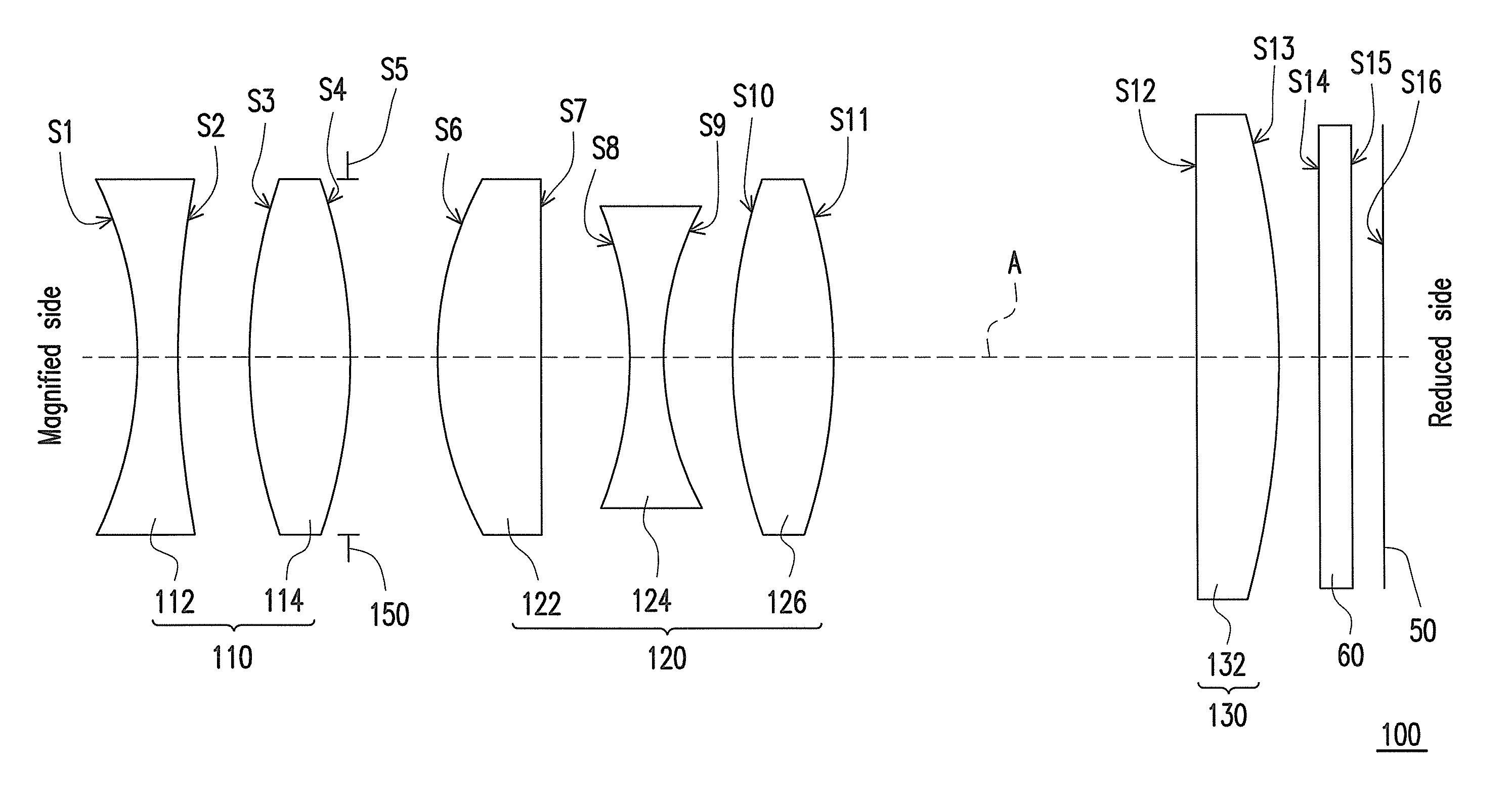
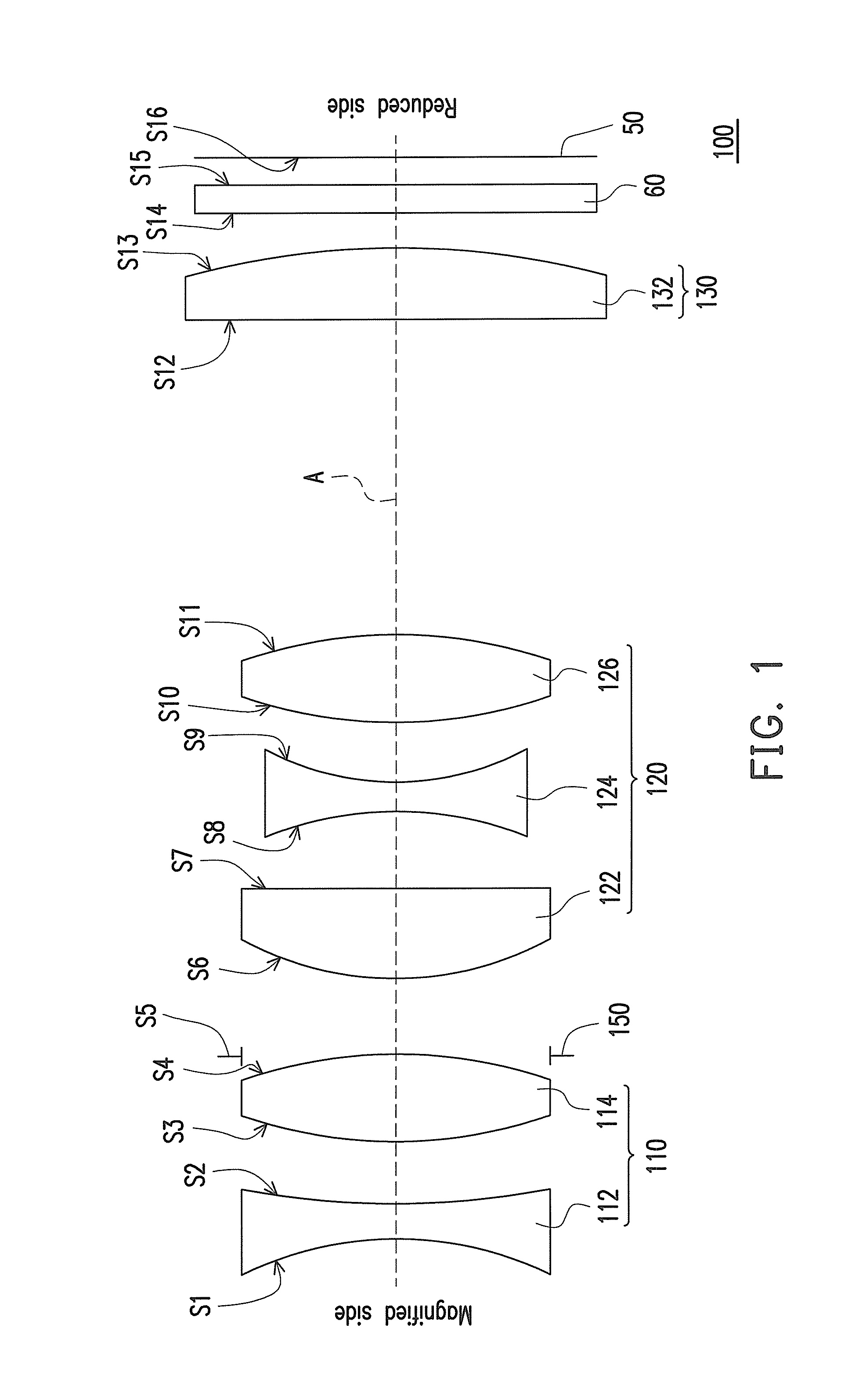
A fixed focal length lens including a first lens group, a second lens group, and a third lens group arranged in sequence from a magnified side towards a reduced side is provided. The first lens group has a positive refractive power, and includes a first lens and a second lens arranged in sequence from the magnified side towards the reduced side. Refractive powers of the first lens and the second lens are respectively negative and positive. The second lens group has a positive refractive power, and includes a third lens, a fourth lens, and a fifth lens arranged in sequence from the magnified side towards the reduced side. Refractive powers of the third lens, the fourth lens, and the fifth lens are respectively positive, negative, and positive. The third lens group has a positive refractive power, and includes a sixth lens. A refractive power of the sixth lens is positive.

Description

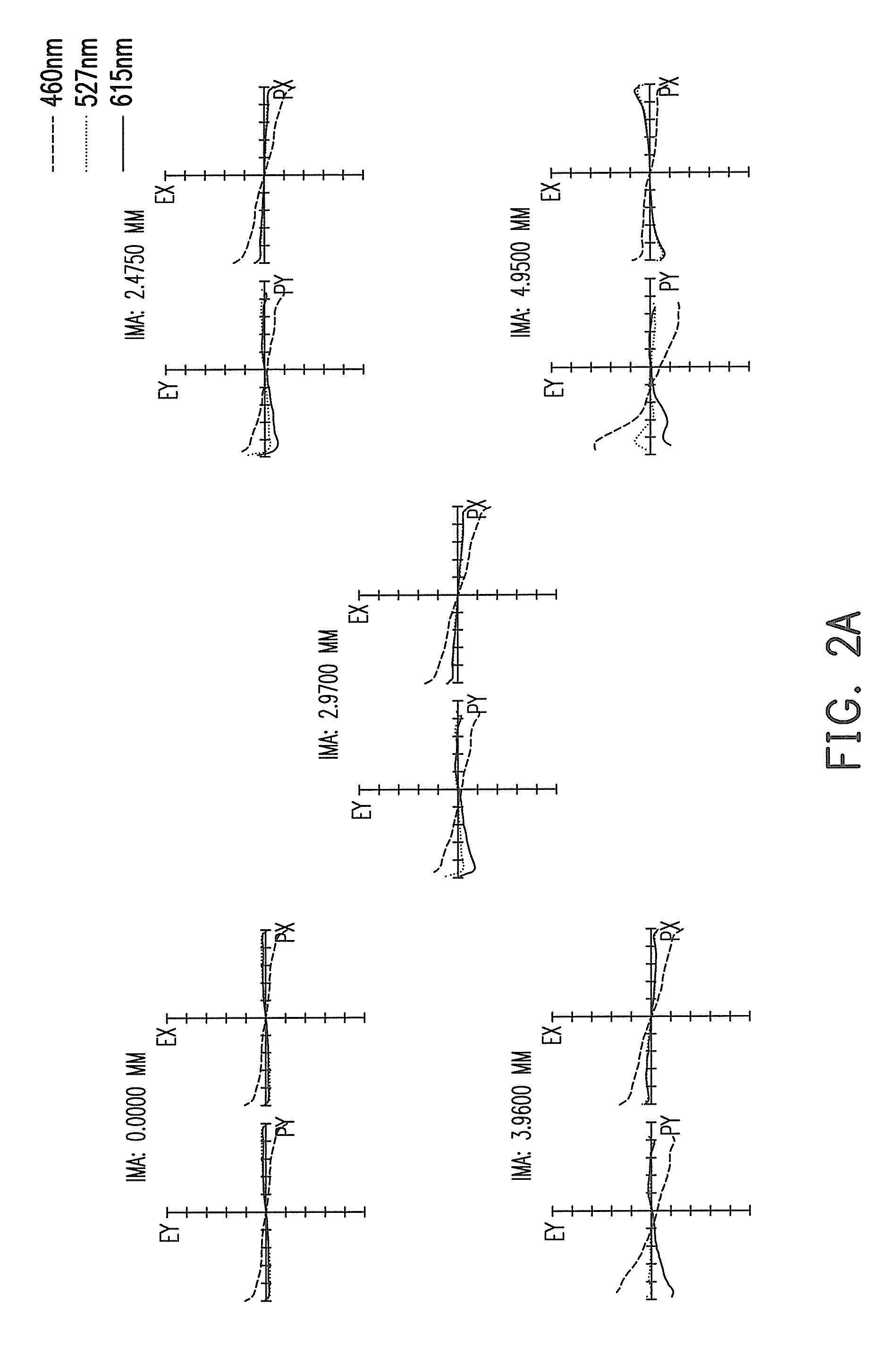
CROSS-REFERENCE TO RELATED APPLICATION[0001]This application claims the priority benefit of Taiwan application serial no. 98134636, filed on Oct. 13, 2009. The entirety of the above-mentioned patent application is hereby incorporated by reference herein and made a part of this specification.BACKGROUND OF THE INVENTION[0002]1. Field of the Invention[0003]The invention relates to a lens, and more particularly relates to a fixed focal length lens.[0004]2. Description of Related Art[0005]Design of a projection lens is a challenge for an optical lens designer. The projection lens with a good performance may have advantages of high image quality, low distortion aberration, high resolution, high contrast, and uniform image illumination. Moreover, to achieve a function of projecting a large image within a short distance, the projection lens may have a large field of view (FOV) and a relatively low distortion aberration. To increase a light efficiency and the illumination uniformity of a pro...

Claims


Application Information

Patent Timeline
Patent Type & Authority Patents(United States)
IPC IPC(8): G02B9/00G02B9/62G02B13/18
CPCG02B13/0045G02B13/16
Inventor WANG, KUO-CHUANLAI, CHING-LUNG
Owner YOUNG OPTICS
Learn More