Induction heating device

a heating device and induction technology, applied in the field of induction heating devices, can solve the problems of excessive heating and easy deformation of the pan, etc., and achieve the effects of reducing the number of infrared ray sensors, improving the measurement accuracy of temperature, and accurate temperature sensing

Active Publication Date: 2013-04-23
PANASONIC CORP
View PDF20 Cites 2 Cited by
  • Summary
  • Abstract
  • Description
  • Claims
  • Application Information

AI Technical Summary

Benefits of technology

[0006]The present invention solves the above disadvantage of the conventional configuration. The present invention provides a user-friendly induction heating device that can prompt, in an easy-to-understand manner, a user to place to-be-heated object 202 at an appropriate position so that sensor 205 can be placed at a position at which the temperature of to-be-heated object 202 can be sensed with a high sensitivity and to-be-heated object 202 is securely placed on sensor 205 to sense the temperature of to-be-heated object 202 accurately.
[0009]Through the configuration as described above, the temperature of a part of the to-be-heated object that has a higher temperature than that of a part corresponding to the center of the heating coil and that is decentered from the center can be sensed in a non-contact manner, thus improving the measurement accuracy of the temperature of the to-be-heated object. Furthermore, the position of the first sensor decentered from the center of the heating coil can be recognized by a user at a position in front of the to-be-heated object at which the user can easily visually recognize the to-be-heated object. This can make the user conscious of the importance of heating the to-be-heated object while the to-be-heated object is located above the first sensor, thus achieving a more accurate temperature sensing. This can prevent the to-be-heated object such as a pan from being abnormally heated or being deformed due to abnormal heating.
[0010]Furthermore, the induction heating device of the present invention has a structure as described below. Specifically, the first sensor that is provided at the lower part of the top plate and that senses the temperature of the to-be-heated object is decentered from the center of the heating coil in a direction vertical to the front side of the main body of the induction heating device so that the first sensor is decentered from the center of the heating coil to a position close to the front side. Thus, the first sensor is placed at a position to sense a part of the to-be-heated object that has a higher temperature than that of a part of the to-be-heated object above the center of the heating coil. A display unit showing the position of the first sensor is provided on the top plate with a reduced number of infrared ray sensors, thus reducing the cost.
[0011]Through the configuration as described above, a part of the to-be-heated object decentered from the center of the heating coil that has a higher temperature than that of a part corresponding to the center of the heating coil can be sensed. Furthermore, the position of the first sensor that is decentered from the center of the heating coil to a position close to the front side in a direction vertical to the front side of the main body can be sensed by the user at a position in front of the to-be-heated object at which the user can visually recognize the to-be-heated object most easily. This can make the user conscious of the importance of heating the to-be-heated object while the to-be-heated object is located above the first sensor, thus achieving a more accurate temperature sensing. This can prevent the to-be-heated object such as a pan from being abnormally heated or being deformed due to abnormal heating.
[0012]As described above, the induction heating device of the present invention can provide an accurate sensing of a temperature of the to-be-heated object, thus providing improved convenience to users.

Problems solved by technology

This has caused a disadvantage where, when to-be-heated object 202 such as a pan accommodating no food or liquid is heated while to-be-heated object 202 being not placed above sensor 205, the pan may be excessively heated to easily deform for example.

Method used


Image

  • Induction heating device
  • Induction heating device
  • Induction heating device

Examples


embodiment 1

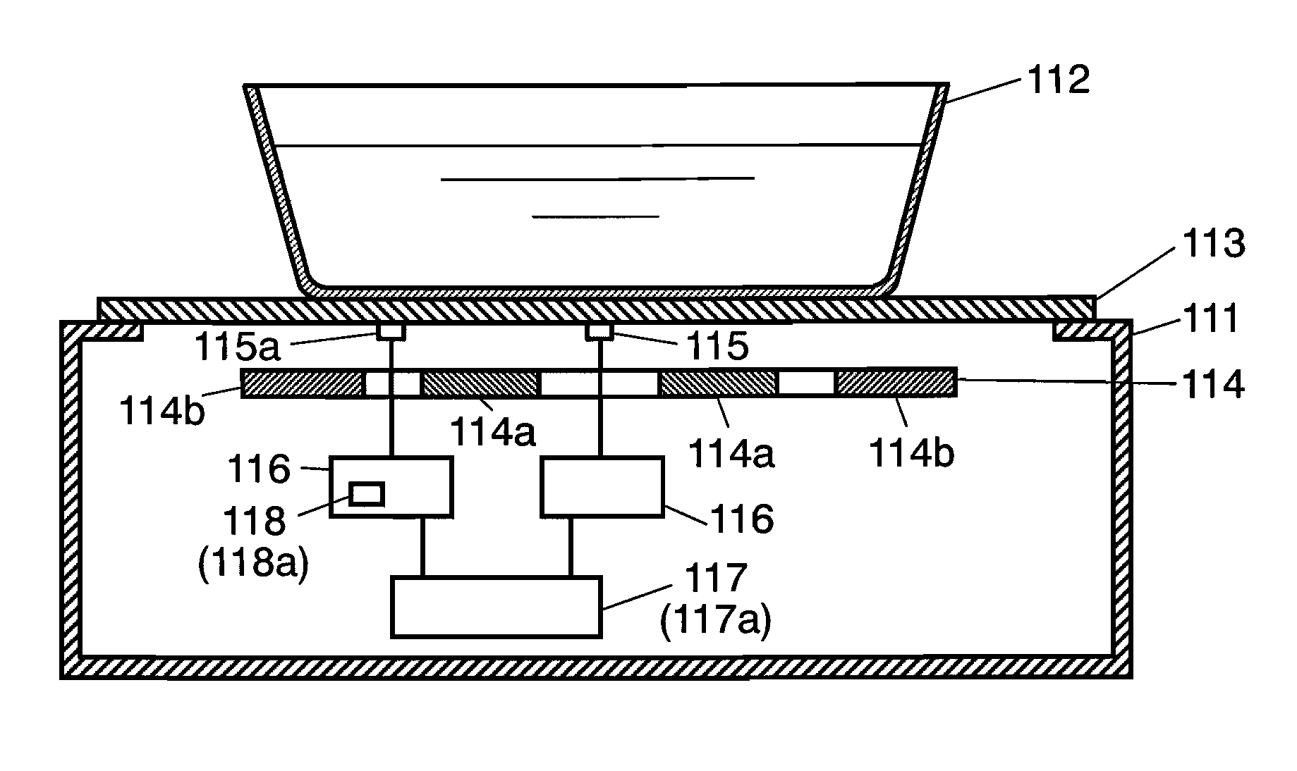
[0043]FIG. 1A is a vertical sectional view illustrating an induction heating device in Embodiment 1 of the present invention seen from a side face. The left side face of FIG. 1A corresponds to the front side of the induction heating device (a side operated by a user).

[0044]It is noted that parts having no direct relation with the description of the present invention will not be shown or described in order to avoid confusion and this will be applied to the entire specification.

[0045]In FIG. 1A, an upper face of main body 111 of the induction heating device has thereon top plate 113 on which to-be-heated object 112 is placed. A lower part of top plate 113 has heating coil 114 for induction-heating to-be-heated object 112.

[0046]Heating coil 114 is divided to inner coils 114a and outer coils 114b. An outer winding of inner coil 114a is connected to an inner winding of outer coil 114b. Inner coil 114a and outer coil 114b are concentrically arranged when seen from the upper side of main b...

embodiment 2

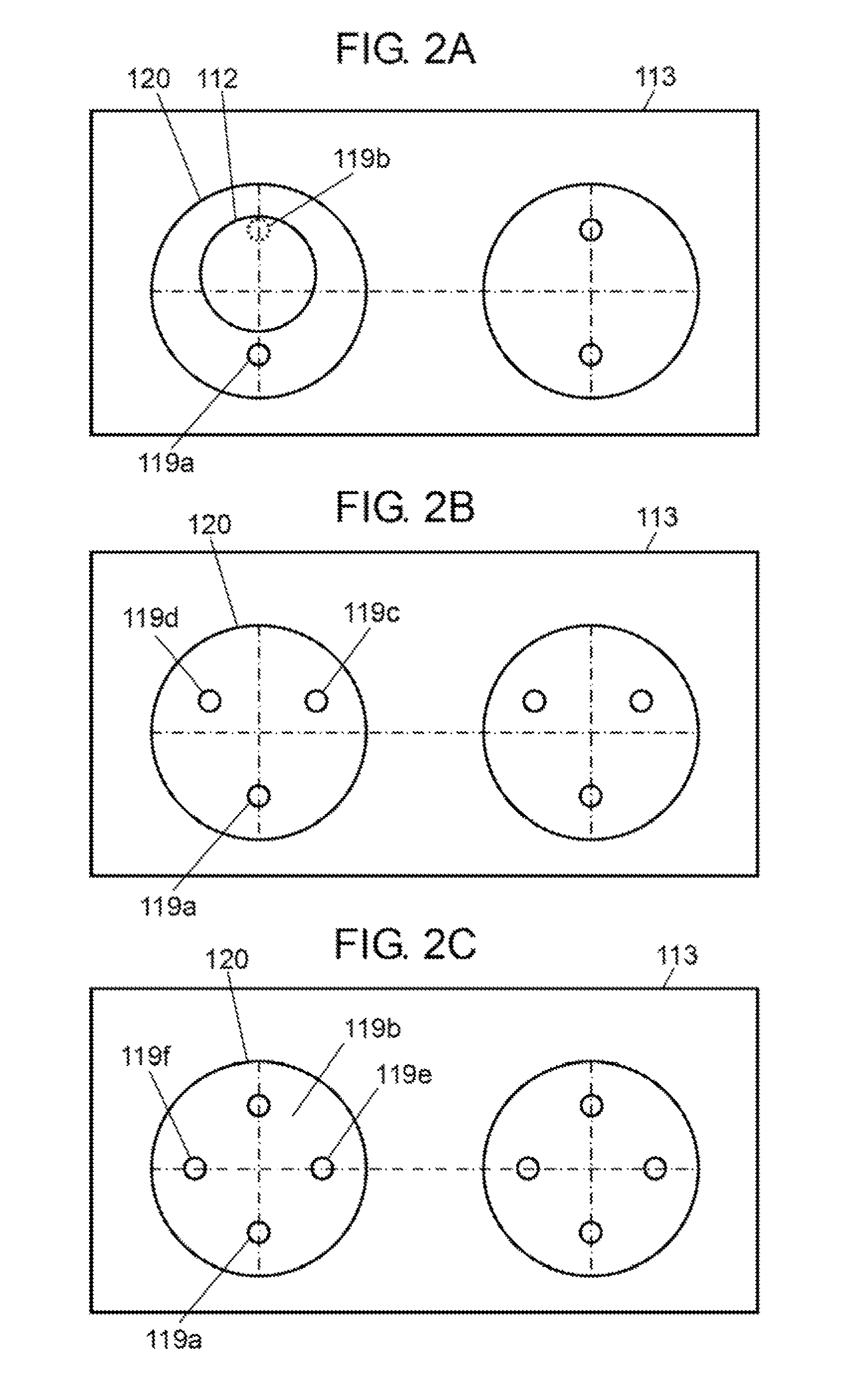
[0062]FIG. 2A, FIG. 2B, and FIG. 2C are plan views illustrating a top plate in Embodiment 2 of the present invention. FIG. 2A shows an example in which two sensors, first sensor 115a and second sensor 115b, are provided (and are provided to correspond to one heating coil 114, respectively hereinafter). FIG. 2B shows an example in which three sensors, first sensor 115a and second sensors 115c and 115d, are provided. FIG. 2C shows an example in which four sensors, first sensor 115a, second sensor 115b, and third sensors 115e and 115f, are provided.

[0063]In Embodiment 2, as shown in the respective drawings, sensors 115a to 115f are provided among the windings of heating coil 114 to sense the temperature of to-be-heated object 112. Sensors 115a to 115f are provided on a single circumference surrounding the center 130 of heating coils 114 so as to divide the circumference into equal circular arcs. First sensor 115a, at one of the equal circular arcs, is placed so as to be decentered from...


PUM


Abstract

An induction heating device has an accurate sensing of the temperature of a to-be-heated object and is user-friendly. The induction heating device includes a sensor for sensing the temperature of the to-be-heated object and can carry out a heating operation only when it is determined that the to-be-heated object exists above the sensor. A display having a circular design and characters, for example, that shows the position of this sensor is provided on a top plate of the induction heating device.

Description

TECHNICAL FIELD[0001]The present invention relates to an induction heating device in which the position of a sensor for sensing a temperature of a to-be-heated object placed on a top plate is decentered from the center of a heating coil and a display showing the position of the sensor is provided on the top plate.BACKGROUND ART[0002]Conventionally, this type of induction heating device is structured, as shown in FIG. 3 that is a vertical sectional view illustrating the induction heating device seen from the front side, a lower part of top plate 203 has heating coil 204 for induction-heating to-be-heated object 202.[0003]Heating coil 204 is divided to inner coil 204a and outer coil 204b. An outer winding of inner coil 204a is electrically connected to an inner winding of outer coil 204b. Inner coil 204a and outer coil 204b are concentrically arranged when seen from the above of main body 201. The center of this concentric pattern corresponds to center 130 of circle 120 of FIG. 1B (wh...

Claims


Application Information

Patent Timeline
Patent Type & Authority Patents(United States)
IPC IPC(8): H05B6/12H05B6/08
CPCH05B6/062H05B6/1272H05B2213/07Y02B40/126H05B6/12Y02B40/00
Inventor KEISHIMA, TOSHIHIROKATAOKA, AKIRANAKAKURA, HIROFUMIHIROTA, IZUO
Owner PANASONIC CORP
Why Eureka
Try Eureka