Stator

a technology of stator and spherical rod, which is applied in the direction of windings, dynamo-electric components, synchronous machines, etc., can solve the problems of high power demand and downsizing of motors to be mounted in vehicles, and achieve the effects of shortening the coil end, avoiding interference, and avoiding interferen

Active Publication Date: 2013-04-23
TOYOTA JIDOSHA KK
View PDF28 Cites 11 Cited by
  • Summary
  • Abstract
  • Description
  • Claims
  • Application Information

AI Technical Summary

Benefits of technology

[0042]The stator in one aspect of the invention configured as above can provide the following operations and advantages.
[0043]In the aspect in (1), a stator comprising: a stator core including teeth and slots formed between the teeth; and coils each being made of a flat rectangular conductor and placed in the slots, wherein each coil has a shape including, in a coil end portion, oblique side portions and a protrusion formed to protrude upward in an axial direction of the stator core from the oblique side portions, the protrusion has a height to avoid interference between the coils placed in the stator core, and the coil end portion of each coil is formed with a lane-change portion, a coil interference-point distance A1 between a first interference point P1 at which a first coil and a second coil arranged adjacently interfere with each other and a second interference point P2 at which the second coil and a third coil arranged adjacently interfere with each other is determined to be equal to or shorter than a bending center-to-center distance A defined as a distance in a circumferential direction of the stator core between a bending center on an inner circumferential side of the lane-change portion located on the inner circumferential side of the stator core and a bending center on an outer circumferential side of the lane-change portion located on the outer circumferential side of the stator core.
[0044]Since the protrusion protruding from the oblique side portions in the coil end of the coil, it is easier to avoid the interference between coils when the coils are inserted in the stator core. Thus, shortening of the coil ends is achieved.
[0045]The coil end portions of the stator need to be arranged to avoid the interference between the coils. However, the coils intersect three-dimensionally in complex form in the coil end portions. Accordingly, it is possible to form the protrusions in order to avoid the interference with the adjacent coils. Avoiding the interference enables efficient shortening of the coil end portions.
[0046]For instance, when a coil is to be wound into a hexagonal form, two sides in a coil end protrude like an isosceles triangle. In this case, if isosceles triangular portions of the coils are arranged to detour around one another, a distance (an interval) needs to be provided between the coils in view of the thickness of the flat rectangular conductor (conductor wire). Accordingly, a width (range) is required for lane change. However, the first protrusion and the second protrusion provided in each coil can facilitate avoidance of the interference between the adjacent coils.
[0047]When the first loop and the second loop are to be formed, an edge-wise bending process is necessary in the light of stator structure. However, the first protrusion and the second protrusion are formed by bending the conductor in a direction of thinner thickness, not an edge-wise bending direction. Thus, a bending radius is small and hence the conductor can be bent relatively easily.

Problems solved by technology

However, such motors to be mounted in the vehicles are demanded for high power and downsizing.

Method used


Image

  • Stator
  • Stator
  • Stator

Examples


first embodiment

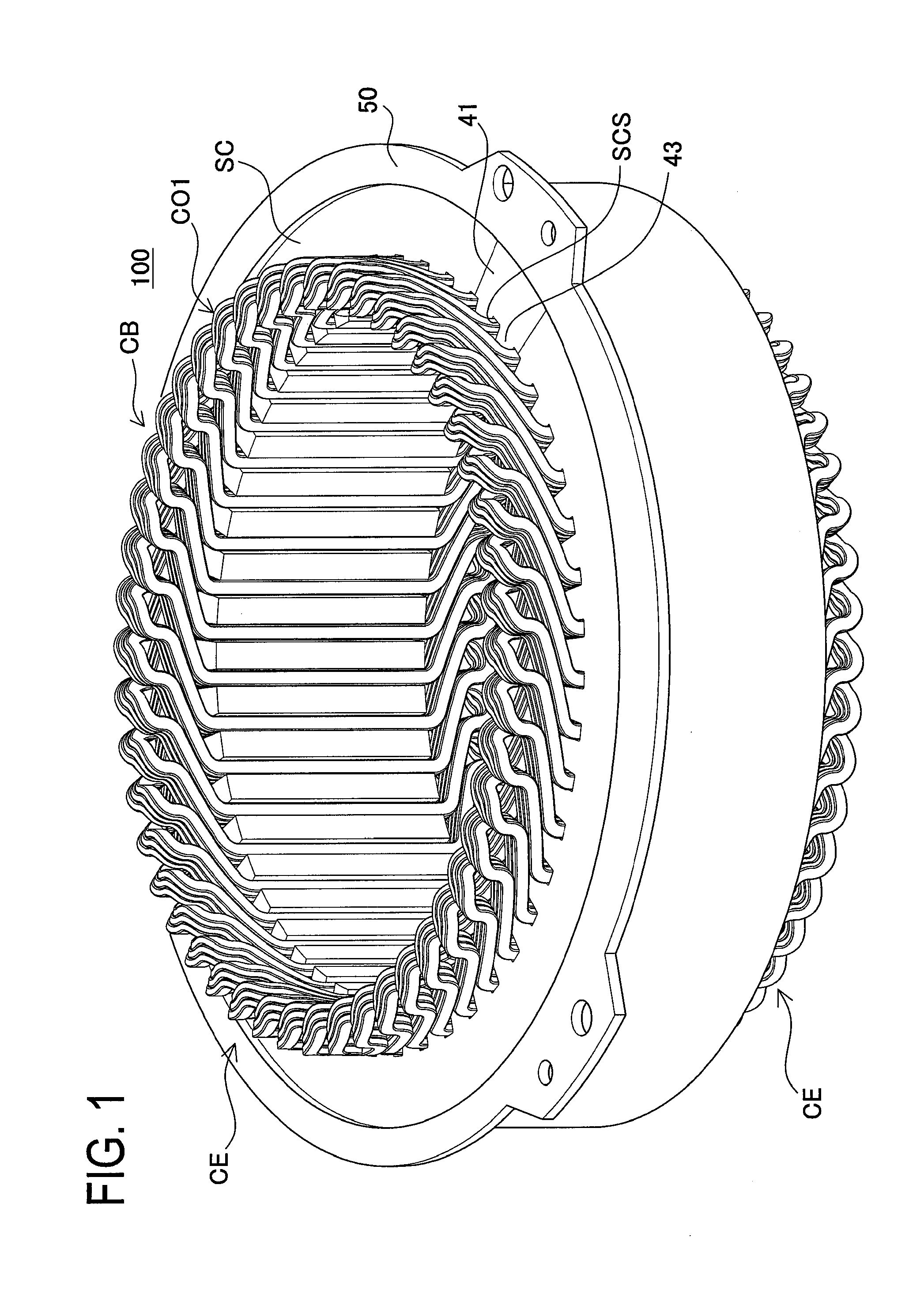
[0122]FIG. 1 is a perspective view of a stator in the first embodiment.

[0123]A stator 100 includes protrusion-formed coils CO1, a split stator core SC, and an outer ring 50. It is to be noted that a terminal stand 55 and bus bars BB shown in FIG. 17 should be provided in a coil end CE to complete the stator 100 but they are not illustrated in FIG. 1 for facilitating the explanation of lane change.

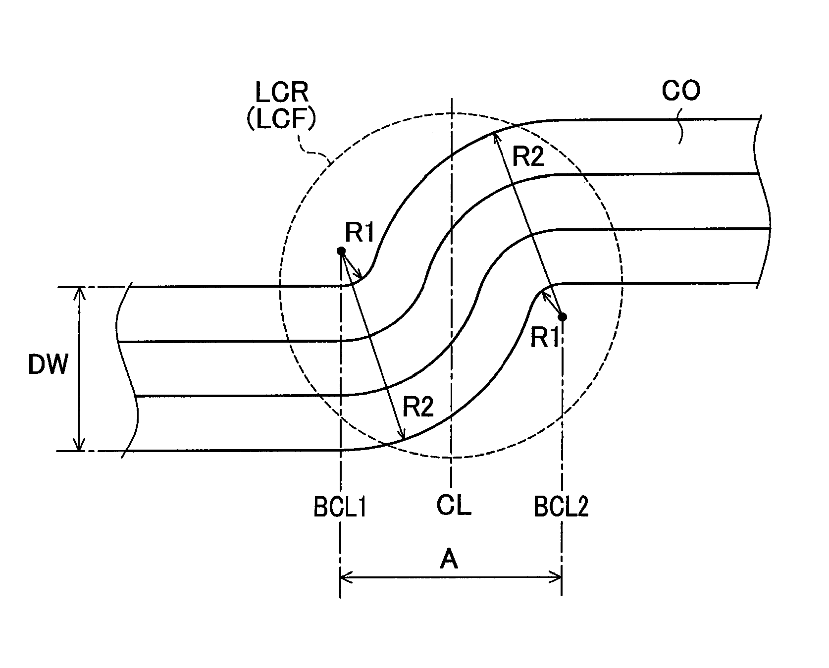
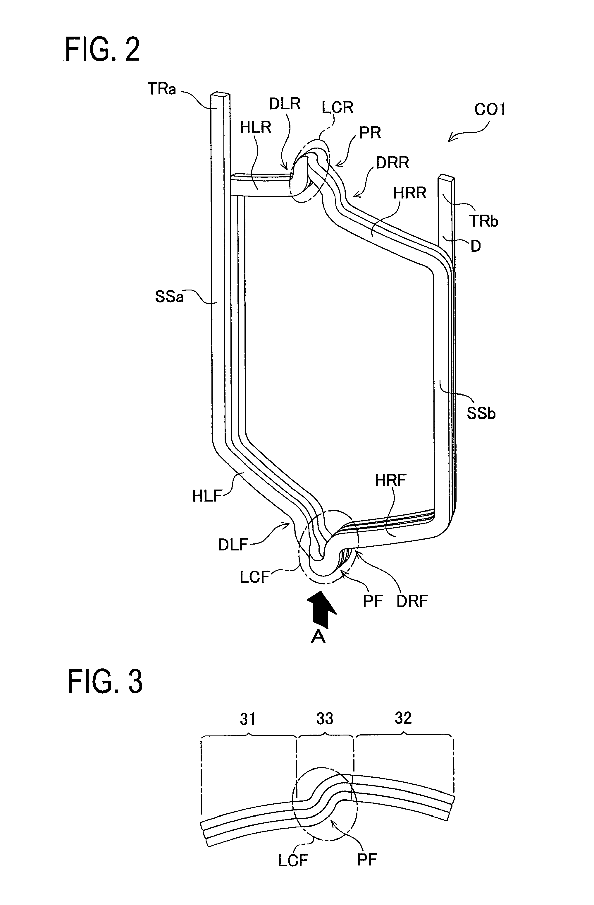
[0124]FIG. 2 is a perspective view of each protrusion-formed coil. FIG. 3 is a lower view of the protrusion-formed coil, seen from an arrow A in FIG. 2.

[0125]The protrusion-formed coil CO1 is made, as shown in FIG. 2, by winding a flat rectangular conductor (conductor wire) D in three turns by edge-wise bending, so that a first terminal portion TRa and a second terminal portion TRb are provided.

[0126]The protrusion-formed coil CO1 further includes a first oblique side portion HLR, a second oblique side portion HRR, a third oblique side portion HLF, and a fourth oblique side portion HRF. In ...

second embodiment

[0184]A stator 100 in the second embodiment is almost the same in structure as the stator 100 in the first embodiment, excepting that a one-side protrusion-formed coil CO3 in the second embodiment corresponding to the protrusion-formed coil CO1 in the first embodiment is slightly different in structure of a coil end CE from the protrusion-formed coil CO1.

[0185]FIG. 12 is a perspective view of the one-side protrusion-formed coil in the second embodiment.

[0186]The one-side protrusion-formed coil CO3 includes, as shown in FIG. 12, a first oblique side portion HLR, a second oblique side portion. HRR, a third oblique side portion HLF, and a fourth oblique side portion HRF. A lead-side protrusion PR is formed in an extension of the first oblique side portion HLR. The second oblique side portion HRR is formed linearly to a lead-side lane-change portion LCR. A non-lead-side protrusion PF is formed in an extension of the third oblique side portion HLF. The fourth oblique side portion HRF is ...

third embodiment

[0195]A stator 100 in the third embodiment is substantially identical in structure to the stator 100 in the second embodiment, excepting that a one-side protrusion-formed coil CO4 in the third embodiment corresponding to the one-side protrusion-formed coil CO3 is slightly different in structure of a coil end CE from the coil CO3.

[0196]FIG. 15 is a perspective view of the one-side protrusion-formed coil in the third embodiment.

[0197]The one-side protrusion-formed coil CO4 is formed, as shown in FIG. 15, with a first oblique side portion HLR, a second oblique side portion HRR, a third oblique side portion HLF, and a fourth oblique side portion HRF. A lead-side protrusion PR is formed in an extension of the second oblique side portion HRR and the first oblique side portion HLR is formed linearly to a lead-side lane-change portion LCR. A non-lead-side protrusion PF is formed in an extension of the fourth oblique side portion HRF and the third oblique side portion HLF is formed linearly ...


PUM


Abstract

To provide a stator capable of achieving downsizing and high output power and a stator manufacturing method, a stator comprises a split stator core and slots formed between the teeth, and protrusion-formed coils each being made of a flat rectangular conductor and placed in the slots. Each protrusion-formed coil has a shape including, in a coil end portion, a lead-side protrusion or a non-lead-side protrusion formed to protrude upward in an axial direction of the stator core from a first oblique side portion, a second oblique side portion, a third oblique side portion, and a fourth oblique side portion, and a first oblique side portion, a second oblique side portion, a third oblique side portion, and a fourth oblique side portion. The lead-side protrusion or the non-lead-side protrusion is designed with a height to avoid interference between the protrusion-formed coils placed in the stator core.

Description

CROSS-REFERENCE TO RELATED APPLICATIONS[0001]This is a 371 national phase application of PCT / JP2009 / 071147 filed 18 Dec. 2009, the entire content of which is incorporated herein by reference.FIELD OF THE INVENTION[0002]The present invention relates to a technique to improve the space factor of a stator to achieve a downsized and high-power motor.BACKGROUND OF THE INVENTION[0003]In recent years, the needs for hybrid electric vehicles, electric vehicles, and others have been increased. Accordingly, motors have been studied to be used for the driving power of vehicles. However, such motors to be mounted in the vehicles are demanded for high power and downsizing. Particularly, hybrid electric vehicles are strictly demanded for size reduction in view of the placement of a motor in an engine room.[0004]Therefore, various studies have been made to achieve downsizing and high power of motors.[0005]Patent Literature 1 discloses a technique related to a conductor part for stator frame in a mu...

Claims


Application Information

Patent Timeline
Patent Type & Authority Patents(United States)
IPC IPC(8): H02K3/04H02K15/04
CPCH02K3/12H02K15/045H02K15/0081H02K2213/03H02K3/04
Inventor WATANABE, ATSUSHIANDO, FUJIOHAGA, MASAYOSHIKITAMURA, MANABU
Owner TOYOTA JIDOSHA KK
Why Eureka
Try Eureka