Agricultural working vehicle

a working vehicle and agricultural technology, applied in the field of agricultural working vehicles, can solve the problems of requiring a great deal of skill on the part of the operator, a large amount of time to optimize the setting parameters, and it is difficult for untrained operators of the working vehicle in particular to select the optimal setting

Active Publication Date: 2013-04-23
CLAAS SELBSTFAHRENDE ERNTEMASCHINEN GMBH
View PDF12 Cites 28 Cited by
  • Summary
  • Abstract
  • Description
  • Claims
  • Application Information

AI Technical Summary

Benefits of technology

[0006]The object of the present invention is to avoid the disadvantages of the related art described above, and, in particular, to provide an agricultural working vehicle such that even an untrained operator may optimize the setting parameters of the working assemblies rapidly and reliably.
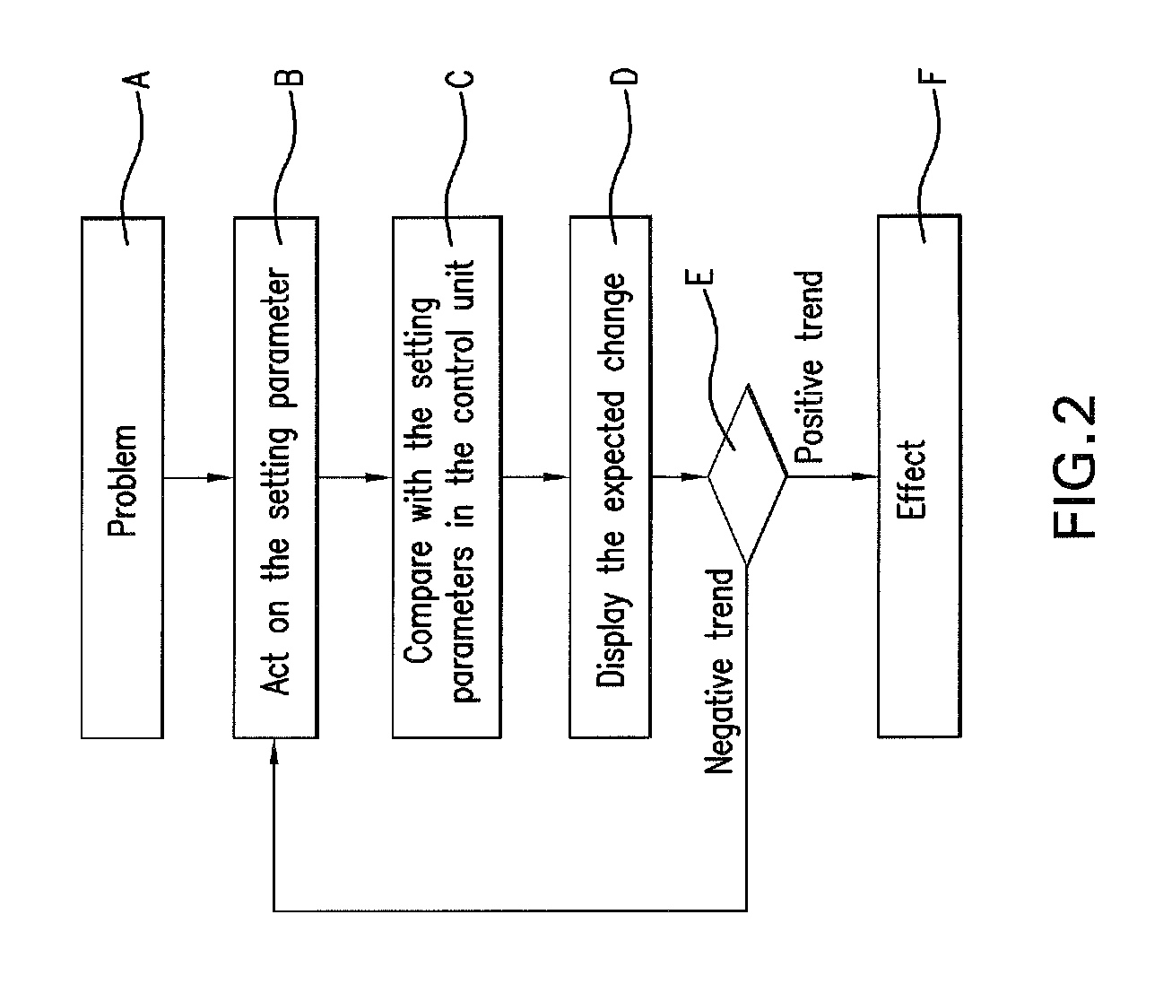
[0008]The depiction of the expected change in the function and / or the working result of individual working assemblies or a plurality of working assemblies therefore also enables an inexperienced operator to directly and rapidly assess the effects of the change he made to the setting parameters of the working assemblies without these effects having been noticeable. What is basically involved here is not changes to the function and / or the working result that are exactly definable using numbers, but rather a visualization of the trend of the expected effects of the operator's actions. This direct and immediate depiction of the expected effects then prompts the operator to immediately influence the setting parameters—when the expected effects are negative—such that he may immediately attain a positive function and / or a positive working result of individual working assemblies or a plurality of working assemblies.
[0011]In an advantageous refinement of the present invention, in order to continually increase the database, and, therefore, to improve the quality of the statement regarding the expected change to the function and / or the working result, setting parameters and / or functions and / or working results that deviate from the setting parameters stored in the memory unit along with their influence on the function and / or the working result of individual working assemblies or a plurality of working assemblies are stored in the memory unit in a recallable manner.
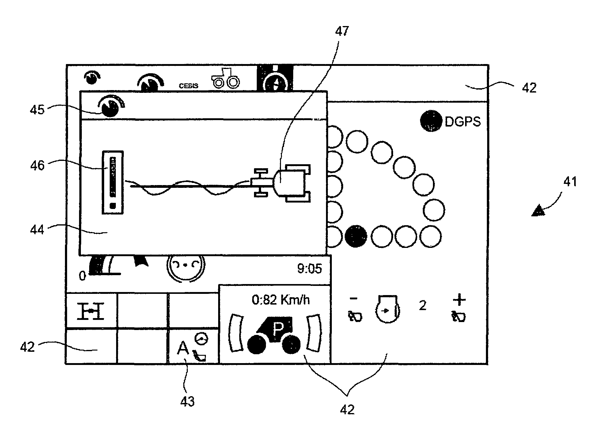
[0012]The expected changes are communicated in a visually rapid and simple manner to an untrained operator of the agricultural working vehicle in particular by depicting the expected change in the function and / or the working result of individual working assemblies or a plurality of working assemblies in the display unit in the form of various pictograms. It is particularly advantageous when the shape and / or color and / or size of the pictograms depicted in the display unit differ in a manner that depends on the expected change in the function and / or the working result of individual working assemblies or a plurality of working assemblies. Possible pictograms depend on the associated effect and include a large number of known forms, such as exclamation points, arrows, smiley faces, frowning faces, hand figures with the thumb pointing up or down, etc. It is also feasible to display the pictograms in color depending on the effect to be communicated, e.g., in red if the effects are expected to be negative, and green if the effects are expected to be positive.
[0013]In an advantageous refinement, in order to avoid overwhelming the operator with information and to be able to show him the actual effects of his influence on the setting parameters in the display unit as quickly as possible, an expected change to the function and / or the working result of individual working assemblies or a plurality of working assemblies is depicted in the display unit only for a certain period of time.
[0014]To make it even easier for an untrained operator, in particular, to identify the optimal setting parameters, an advantageous refinement of the present invention is designed such that a large number of setting parameters is stored in a recallable manner in the memory unit along with their influence on the function and / or the working result of individual working assemblies or a plurality of working assemblies, which are compared with the current setting parameters influenced by the operator, in order to depict an expected change in the function and / or working result in the display unit, and, if the change in the function and / or working result is expected to be negative, the operator is also shown setting parameters that are stored in the memory unit that would bring about a positive change in the function and / or working result. The operator is therefore shown not only the trend of the expected effects, but he is also shown an option for adjusting the setting parameters that would result in an optimal function and / or an optimal working result.

Problems solved by technology

Since there are highly complex interrelationships between the individual working assemblies and their influence on the working result, however, the setting parameters often have a nonlinear influence on the working result, and since the setting parameters that are required to attain a certain function or a certain working result are subject to strong hysteresis, it is difficult for untrained operators of the working vehicle in particular to select the optimal setting parameters for the working assemblies.
The disadvantage of the known method is that, due to the time delay between the particular start of the harvesting operation and the sensor-supported registration of the working result that is attained, a great deal of time is required to optimize the setting parameters.
It is also disadvantageous that the operator must repeatedly try to attain a nearly constant crop material throughput rate in order to ensure that the working results obtained with different setting parameters are comparable.
This requires a great deal of skill on the part of the operator and also takes a great deal of time.

Method used


Image

  • Agricultural working vehicle
  • Agricultural working vehicle
  • Agricultural working vehicle

Examples


Embodiment Construction

[0022]A schematicized side view of an agricultural working vehicle designed as a combine harvester 1 is shown in FIG. 1, as an example. The object of a combine harvester 1 is to pick up the crop material growing on stalks from a field 32 and separate it from the straw and other admixtures. A grain cutting device 2, which is used to pick up the crop material, is shown in FIG. 1 as an example. It cuts the crop stalks with the crop material in the ears out of field 32 and combines them across the width of feeder 3, which performs the intake function. Located in feeder 3 are rotating feed chains 4 with transverse segments that feed the crop material to downstream threshing units 5, 6. The crop material is removed by preacceleration cylinder 5 at the end of feed rake 3 and is accelerated around the circumference of preacceleration cylinder 5 between preacceleration cylinder 5 and concave 8. The accelerated crop material is then transferred to cylinder 6. The crop material is separated fr...


PUM


Abstract

An agricultural working vehicle has a plurality of working assemblies, at least one control unit for influencing the setting parameters of the working assemblies, a memory unit, and at least one display unit, and it is configured such that even an untrained operator may optimize the setting parameters of the working assemblies in a rapid, reliable manner. An expected change in the function and / or the working result of individual working assemblies or a plurality of working assemblies is depicted in the display unit in a manner that depends on how an operator influences individual setting parameters of the working assemblies.

Description

CROSS-REFERENCE TO RELATED APPLICATION[0001]The invention described and claimed hereinbelow is also described in German Patent Applications DE 10 2007 046 678.3 filed on Sep. 27, 2007. This German Patent Application, whose subject matter is incorporated here by reference, provides the basis for a claim of priority of invention under 35 U.S.C. 119(a)-(d).BACKGROUND OF THE INVENTION[0002]The present invention relates to an agricultural working vehicle.[0003]Agricultural working vehicles, e.g., tractors, combine harvesters, forage harvesters, etc., typically include a large number of working assemblies, the setting parameters of which may be influenced by a control unit. With modern agricultural working machines, the function and / or working result of individual working assemblies or a plurality of working assemblies depends essentially on the correct setting parameters of the individual working assemblies and / or their interplay. The correct selection of the setting parameters is theref...

Claims


Application Information

Patent Timeline
Patent Type & Authority Patents(United States)
IPC IPC(8): G06F7/70G06G7/00G06F19/00G06G7/76
CPCA01D41/127
Inventor DIEKHANS, NORBERTMEYER ZU HELLIGEN, LARS PETER
Owner CLAAS SELBSTFAHRENDE ERNTEMASCHINEN GMBH
Why Eureka
Try Eureka