Dual recycling-type coin changer

a coin changer and recycling type technology, applied in the direction of coin dispensers, instruments, apparatus with change giving, etc., can solve the problem that the user of the other one may not be kept waiting lik

Inactive Publication Date: 2013-04-30
ASAHI SEIKO CO LTD
View PDF3 Cites 1 Cited by
  • Summary
  • Abstract
  • Description
  • Claims
  • Application Information

AI Technical Summary

Benefits of technology

[0018]Therefore, a first object of the present invention is to provide a small recycling-type coin changer which enables coins to be inserted thereinto at the same time from opposite sides by different users and processed efficiently.
[0019]A second object of the present invention is to provide a recycling-type coin changer which is user-friendly for disabled people and elderly people.
[0020]A third object of the present invention is to provide a recycling-type coin changer which is inexpensive, compact and can be integrated into a commercial stand-alone kiosk such as in a gas station or a store.
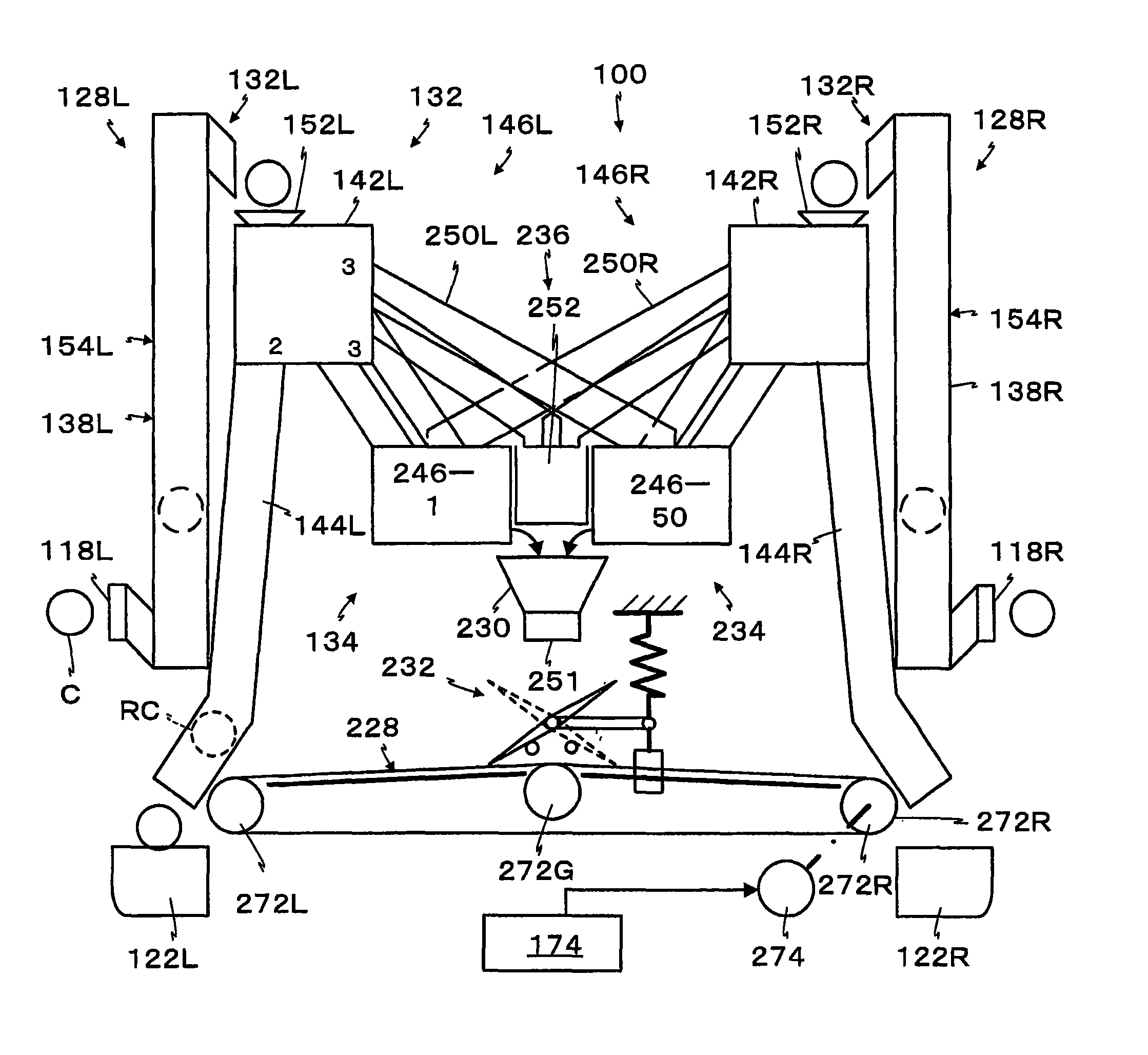
[0022]The recycling-type coin changer has a pair of coin sorting devices each individually provided to correspond to a specific coin inlet, and can discriminate the genuineness / counterfeit and the denomination of the put-in coin, while returning a counterfeit coin to the corresponding coin outlet, and distributing the genuine coin to an exit corresponding to the denomination. A pair of return passages can each directly guide a return coin from a return opening to the corresponding coin outlet by gravity. A pair of denomination-sorted coin passages can guide a coin from denomination-sorted exits of the pair of coin sorting devices to a common denomination-sorted coin holding device by gravity. The coin holding device can be aligned in parallel rows around a centrally located common duct in the housing.
[0023]The common duct can guide the denomination-sorted coin dispensed from the common denomination-sorted coin holding device onto a coin-discharging belt by gravity. A coin-discharging belt is directly mounted below the common duct and suspended between the pair of coin outlets to be selectively moved toward one of the coin outlets which can be on respective opposite walls of the housing.
[0024]A turning shaft is disposed below an exit of the common duct, between the coin falling opening and the coin-discharging belt, and in parallel to the coin-discharging belt. A distributing plate is mounted to the turning shaft to extend in mutually-opposed directions and more integrally with the turning shaft in a path of a fallen coin. Each of the ends of the distributing plate can be moved to a position close to an upper surface of the coin-discharging belt so that the distance between the end and the upper surface is smaller than the thickness of a thinnest coin.

Problems solved by technology

Therefore, there is a problem that a customer who wants to use the other coin inlet unit has to wait until usage of the coin input unit, which is in use, is finished.
Therefore, the user of the other one may not be kept waiting like the first conventional technique.

Method used


Image

  • Dual recycling-type coin changer
  • Dual recycling-type coin changer
  • Dual recycling-type coin changer

Examples


Embodiment Construction

[0040]Reference will now be made in detail to the preferred embodiments of the invention which set forth the best modes contemplated to carry out the invention, examples of which are illustrated in the accompanying drawings. While the invention will be described in conjunction with the preferred embodiments, it will be understood that they are not intended to limit the invention to these embodiments. On the contrary, the invention is intended to cover alternatives, modifications and equivalents, which may be included within the spirit and scope of the invention as defined by the appended claims. Furthermore, in the following detailed description of the present invention, numerous specific details are set forth in order to provide a thorough understanding of the present invention. However, it will be obvious to one of ordinary skill in the art that the present invention may be practiced without these specific details. In other instances, well known methods, procedures, components, an...


PUM


Abstract

A compact recycling coin changer device for simultaneously serving a plurality of users includes a housing with a plurality of coin inlet and outlet slots. Individual coin lift units deliver coins for sorting and distributing to common coin denomination hoppers are arranged in parallel rows. A common duct, centrally located in the housing, can receive released coins from the hoppers and deposit them on a common coin-distributing device that operatively interconnects with the respective coin outlets, for example on opposite exterior housing walls. The coin changer device can be operatively associated with the dispensing of products, for example at a gas station or other retail outlets.

Description

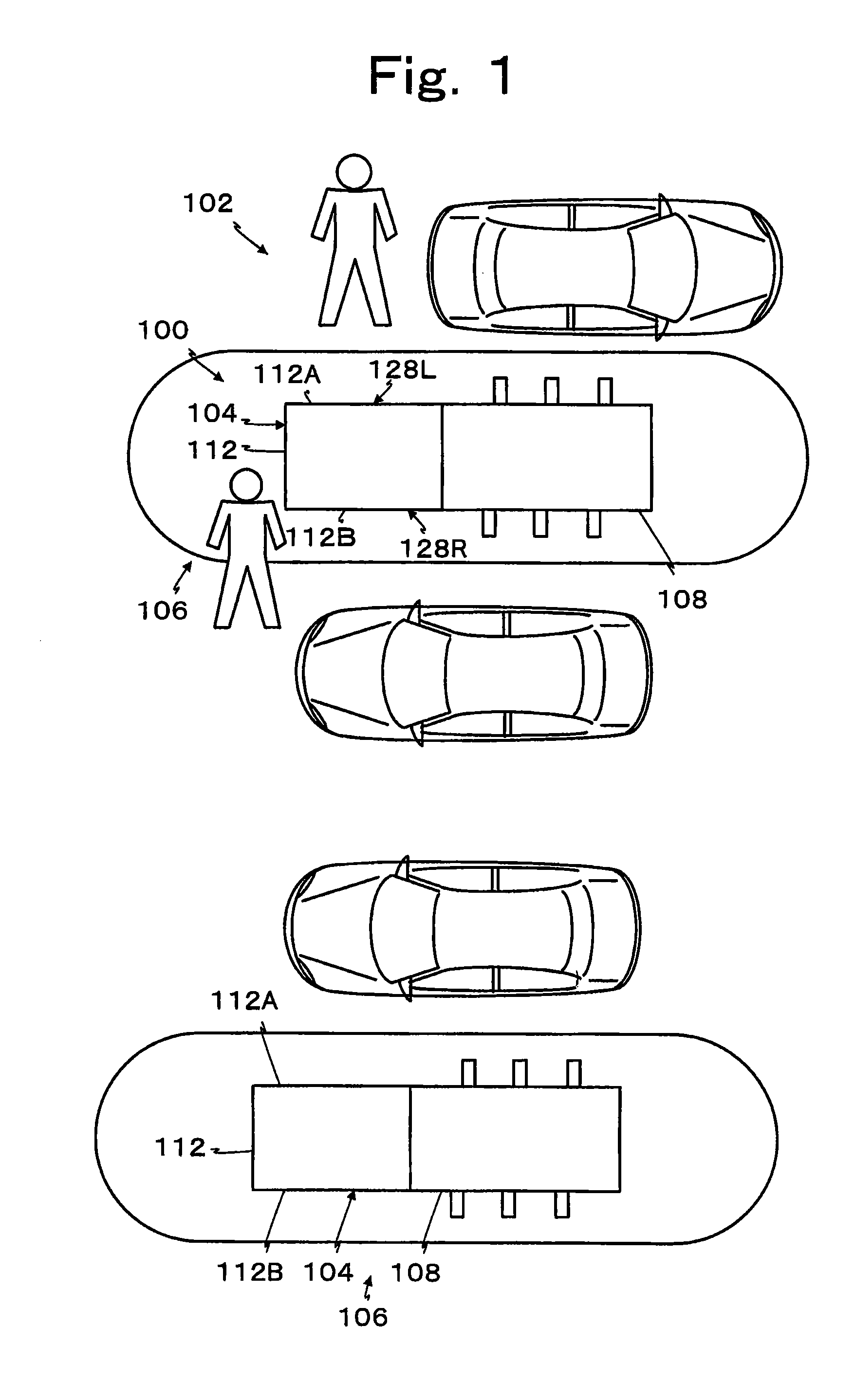
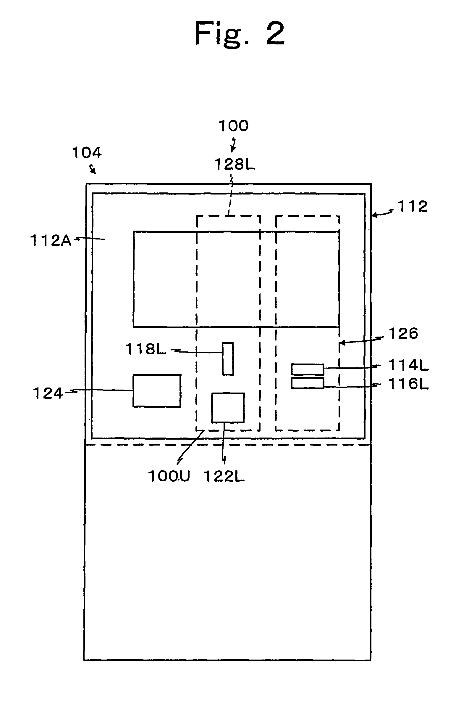
CROSS-REFERENCE TO RELATED APPLICATION[0001]The present application claims priority from Japanese Patent Application No. JP 2010-112633 filed on May 14, 2010.BACKGROUND OF THE INVENTION[0002]1. Field of the Invention[0003]The present invention relates to a dual recycling-type coin changer in which coin inlets and coin outlets are disposed on mutually-opposed outer surfaces, wherein coins can be simultaneously put into the respective coin inlets disposed on the mutually-opposed outer surfaces by different users at the same time. Particularly, the present invention relates to a recycling-type coin changer in which coin inlets and coin outlets enable coins to be simultaneously inserted into the coin inlets disposed on the mutually-opposed outer surfaces to provide a compact and economical coin changer with shared common components.[0004]2. Description of Related Art[0005]In Japanese Patent No. 4323850, FIGS. 7-9 and Paragraphs 0024 to 0028, there is described a coin handling apparatus ...

Claims


Application Information

Patent Timeline
Patent Type & Authority Patents(United States)
IPC IPC(8): G07F9/10G07F1/04
CPCG07D1/00G07F5/24G07D9/00
Inventor ABE, HIROSHIUMEDA, MASAYOSHI
Owner ASAHI SEIKO CO LTD
Why Eureka
Try Eureka