
Developer, image forming unit and image forming apparatus

a technology of image forming unit and developer, which is applied in the direction of instruments, electrographic process equipment, developers, etc., can solve the problems that conventional image forming units have difficulty maintaining image quality for long periods of tim

Inactive Publication Date: 2013-04-30
OKI DATA CORP
View PDF10 Cites 0 Cited by
  • Summary
  • Abstract
  • Description
  • Claims
  • Application Information

AI Technical Summary

Benefits of technology

[0011]An object of the invention is to maintain acceptable image quality in long periods of time.

Problems solved by technology

Conventional image forming units have difficulty maintaining image quality for long periods of time.

Method used


Image

  • Developer, image forming unit and image forming apparatus
  • Developer, image forming unit and image forming apparatus
  • Developer, image forming unit and image forming apparatus

Examples


first embodiment

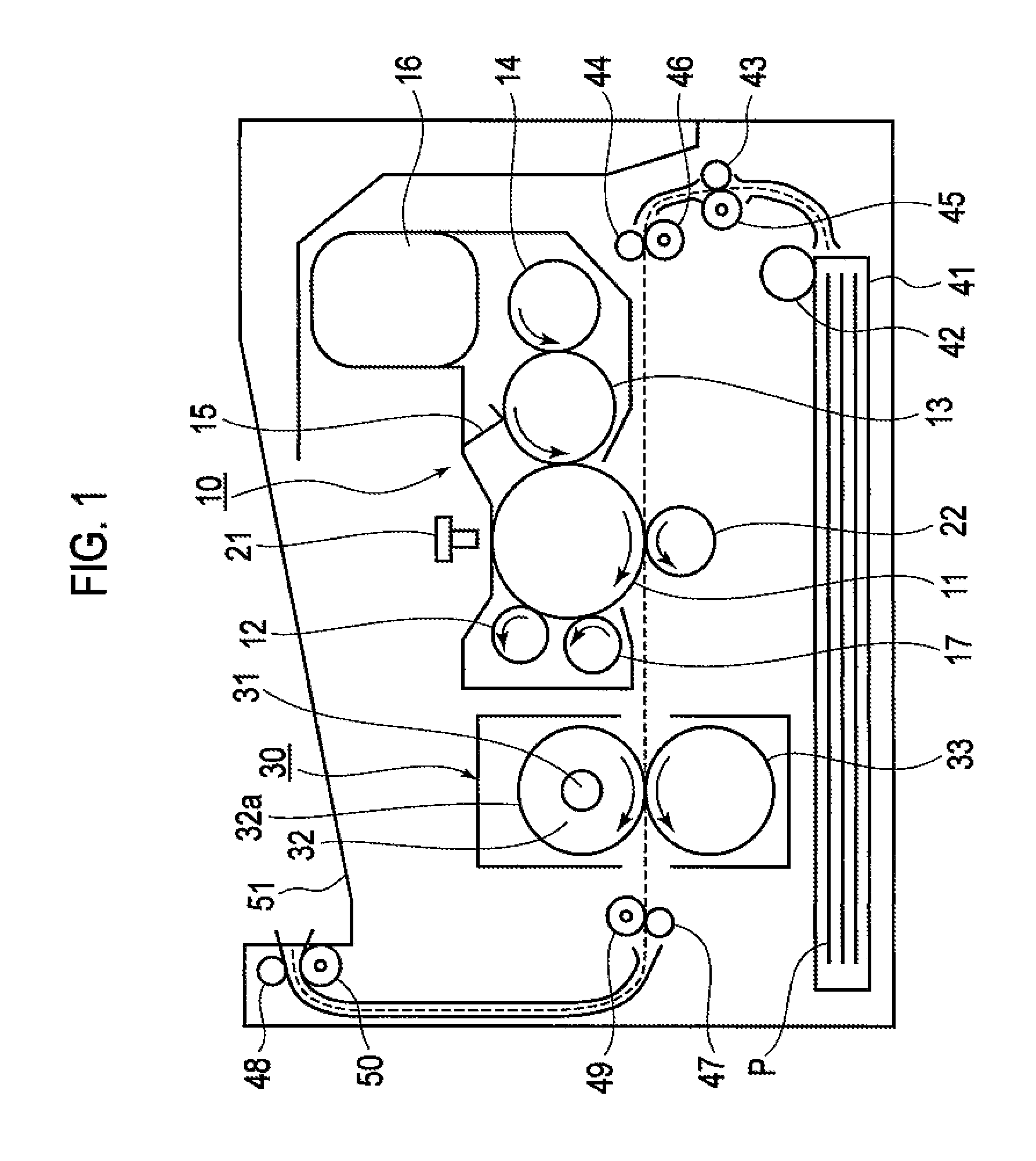
[0022]FIG. 1 is a conceptual diagram of the invention.

[0023]As shown in FIG. 1, a printer includes image forming unit 10 serving as an image former. Image forming unit 10 includes: photosensitive drum 11 serving as an image carrier; charging roller 12 (a charging unit) disposed in contact with the surface of photosensitive drum 11 and configured to uniformly charge the surface of photosensitive drum 11; developing roller 13 serving as a developer carrier disposed in contact with the surface of photosensitive drum 11 and configured to develop a latent image or electrostatic latent image formed on the surface of photosensitive drum 11, thereby forming a toner image (a developer image) on the surface of the photosensitive drum; toner supplying roller 14 (a developer supplying member) disposed in contact with developing roller 13 and configured to supply toner (developer) onto developing roller 13; development blade 15 serving as a developer layer forming member disposed such that its e...


PUM

PropertyMeasurementUnit
Tgaaaaaaaaaa
glass-transition temperatureaaaaaaaaaa
widthaaaaaaaaaa

Abstract

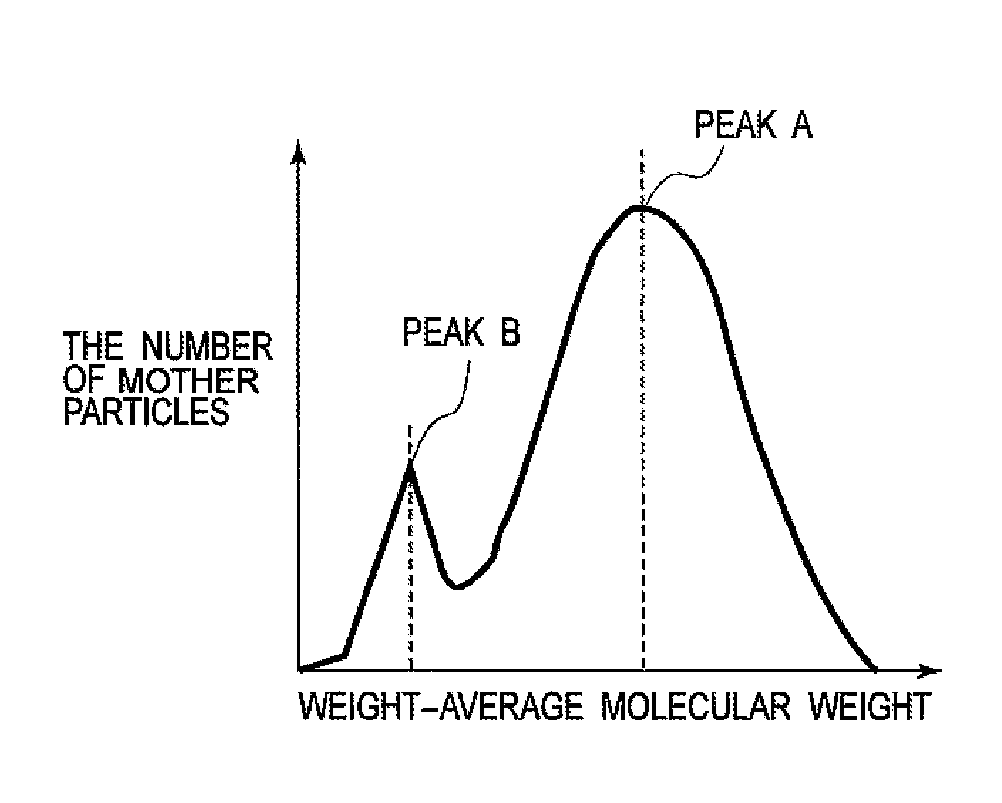
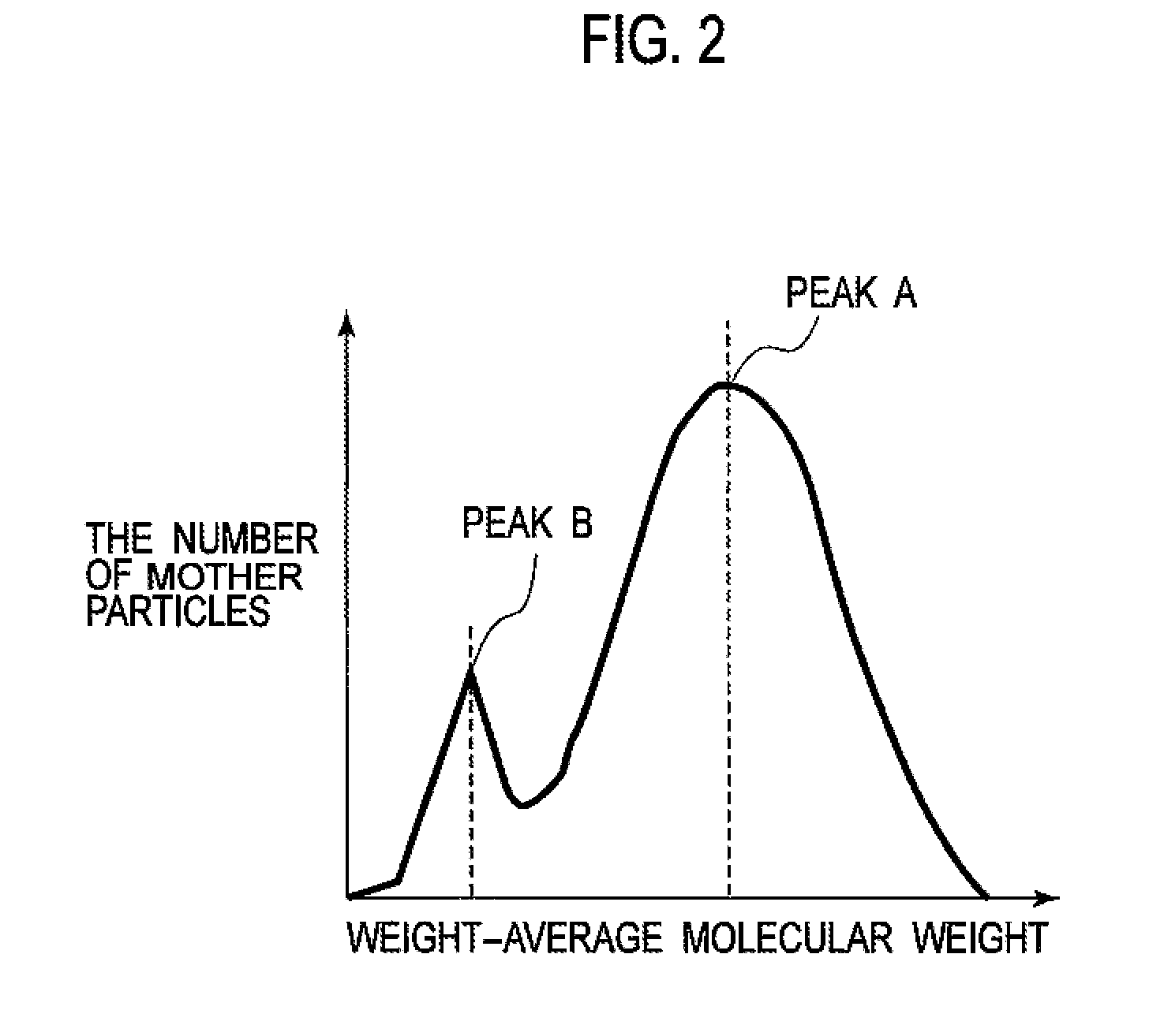
A developer has a molecular weight distribution of its tetrahydrofuran soluble portion measured by a gel permeation chromatography. In the molecular weight distribution, the main peak is in a range from 2×10³ to 3×10⁴ weight-average molecular weight (Mw), the shoulder peak is in a range from 200 to 500 Mw, and a half-value width of the main peak is equal to or less than 50000. A glass-transition temperature Tg of the developer is a range from 55° C. to 80° C.

Description

CROSS REFERENCE TO RELATED APPLICATIONS[0001]This application claims priority based on 35 USC 119 from prior Japanese Patent Application No. 2009-040927 filed on Feb. 24, 2009, entitled “Developer, Image Forming Unit, and Image Forming Apparatus”, the entire contents of which are incorporated herein by reference.BACKGROUND OF THE INVENTION[0002]1. Field of the Invention[0003]The invention relates to a developer, an image forming unit, and an image forming apparatus.[0004]2. Description of Related Art[0005]In an image forming apparatus such as a copy machine, a facsimile machine, an MFP (multi-functional printer or multi-functional peripheral) and the like, for example, in a printer, a charging roller uniformly charges a photosensitive drum, and an LED head exposes light onto the charged photosensitive drum to form an electrostatic latent image on the charged photosensitive drum, and a developing unit develops the electrostatic latent image to from a toner image on the charged photos...

Claims


Application Information

Patent Timeline
Patent Type & Authority Patents(United States)
IPC IPC(8): G03G9/00
CPCG03G9/0821G03G9/08711G03G9/08795G03G9/08797G03G9/09708G03G9/09725G03G2215/0604
Inventor MATSUURA, YUKI
Owner OKI DATA CORP
Learn More