
CT imaging apparatus and methods

a computed tomography and imaging apparatus technology, applied in tomography, instruments, applications, etc., can solve the problems of animal tissue to ionizing radiation, prolonged recovery periods for patients, and over-acquisition of projection images, so as to reduce the amount of dose and effectively monitor the position of patients

Active Publication Date: 2013-11-28
ELEKTA AB
View PDF2 Cites 0 Cited by
  • Summary
  • Abstract
  • Description
  • Claims
  • Application Information

AI Technical Summary

Benefits of technology

The present invention provides a method for getting images while giving less computer tomography (CT) scans to patients. This method helps maintain image quality while keeping track of the patient's position.

Problems solved by technology

It is known that exposure of human or animal tissue to ionizing radiation will kill the cells thus exposed.
In conventional radiation therapy, large volumes of healthy tissue can thus be exposed to harmful doses of radiation, resulting in prolonged recovery periods for the patient.
The limitation of acquiring projection images at a constant rate is that if the gantry slows or stops during a 3D volume / CBCT scan, the number of projection images that are acquired will exceed the number needed to achieve the required image quality.
This means that the patient will have received unnecessary kV exposures, leading to an excessive and inconsistent dose delivered to the patient.
For example, if the rotation of the gantry slows significantly (or even reverses direction), the amount of time between acquisition of successive images may be too long to properly monitor the current position of the patient.

Method used


Image

  • CT imaging apparatus and methods
  • CT imaging apparatus and methods
  • CT imaging apparatus and methods

Examples


Embodiment Construction

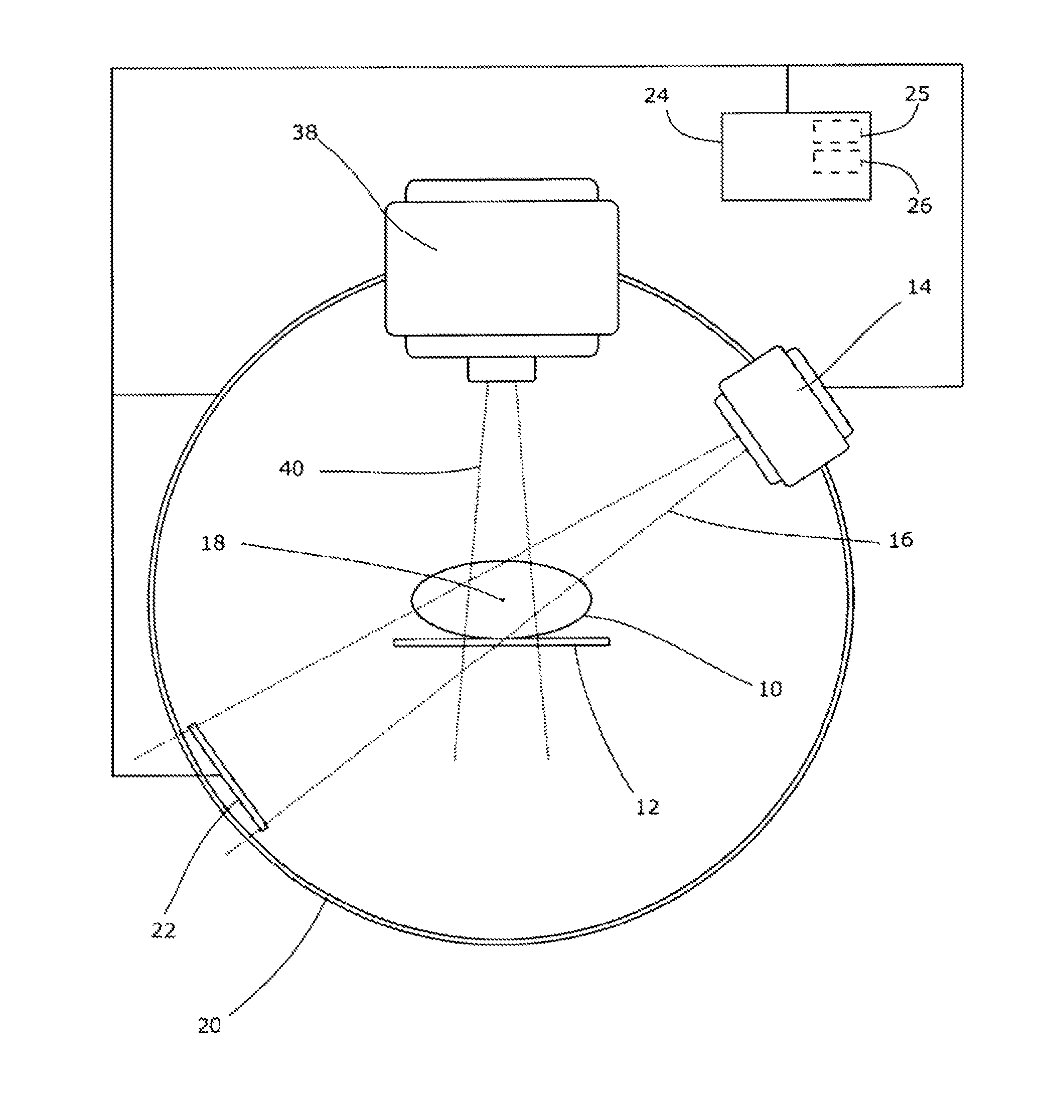
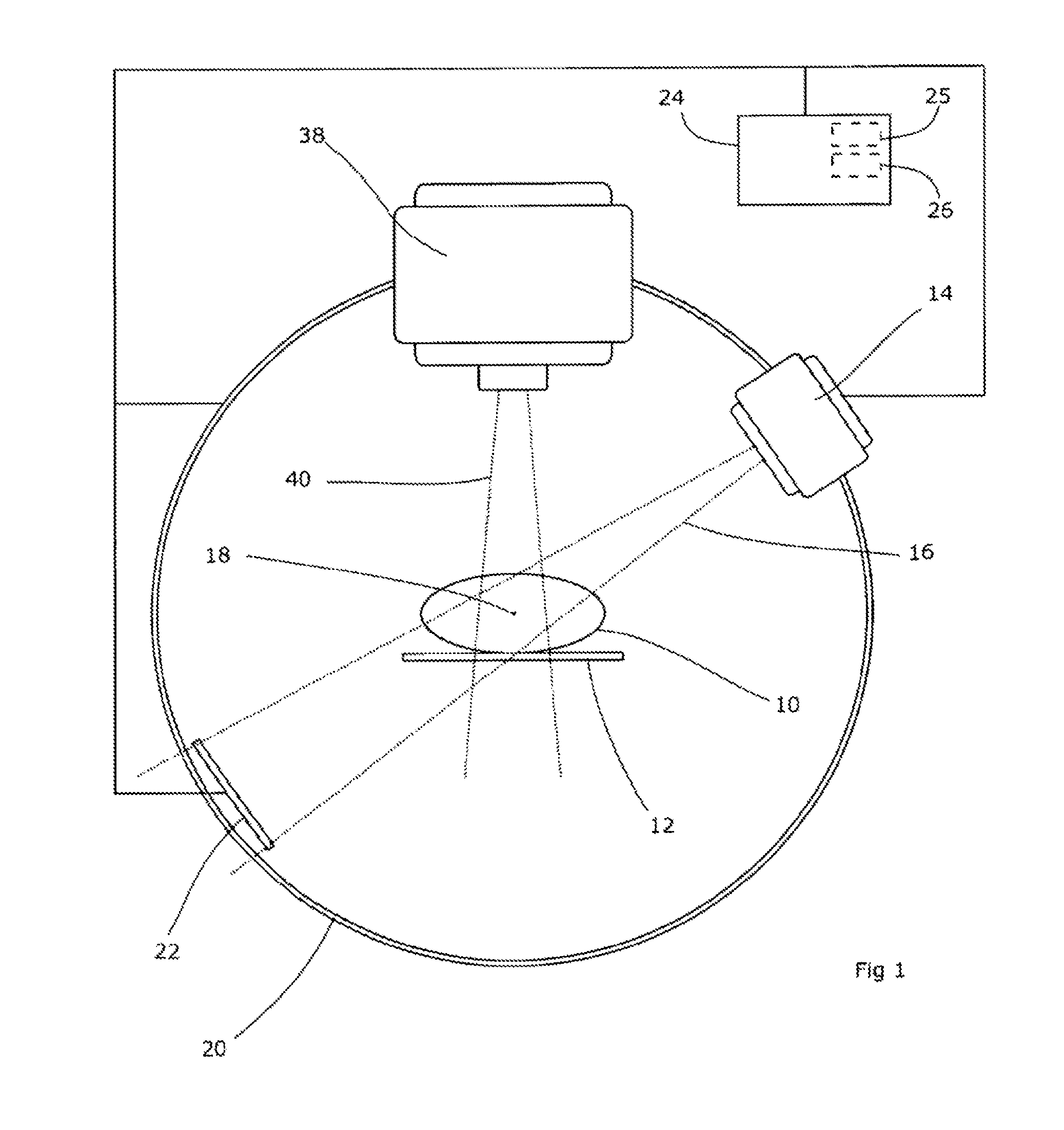
[0018]FIG. 1 is a schematic diagram showing an apparatus according to embodiments of the present invention.

[0019]A patient 10 is supported on a couch 12 which may be of any suitable design. Couches typically allow the elevation, latitudinal and longitudinal position of the patient to be adjusted, and this may be provided for as desired. The couch 12 may also allow rotation in up to three rotational degrees of freedom (pitch, yaw and roll).

[0020]An x-ray source 14 is arranged to project a wide beam 16 of radiation generally directed towards the isocenter 18 of the system. The source 14 is rotatable around the isocenter 18 on a rotational support 20. The support can, for example, be in the form of a ring or annulus around the patient 10 and couch 12 in which the source is mounted, or it can be a C-arm, or any suitable support allowing the source to rotate, or any combination thereof. The radiation beam 16 will generally have an energy in the kV range, as that is most suitable for imag...


PUM


Abstract

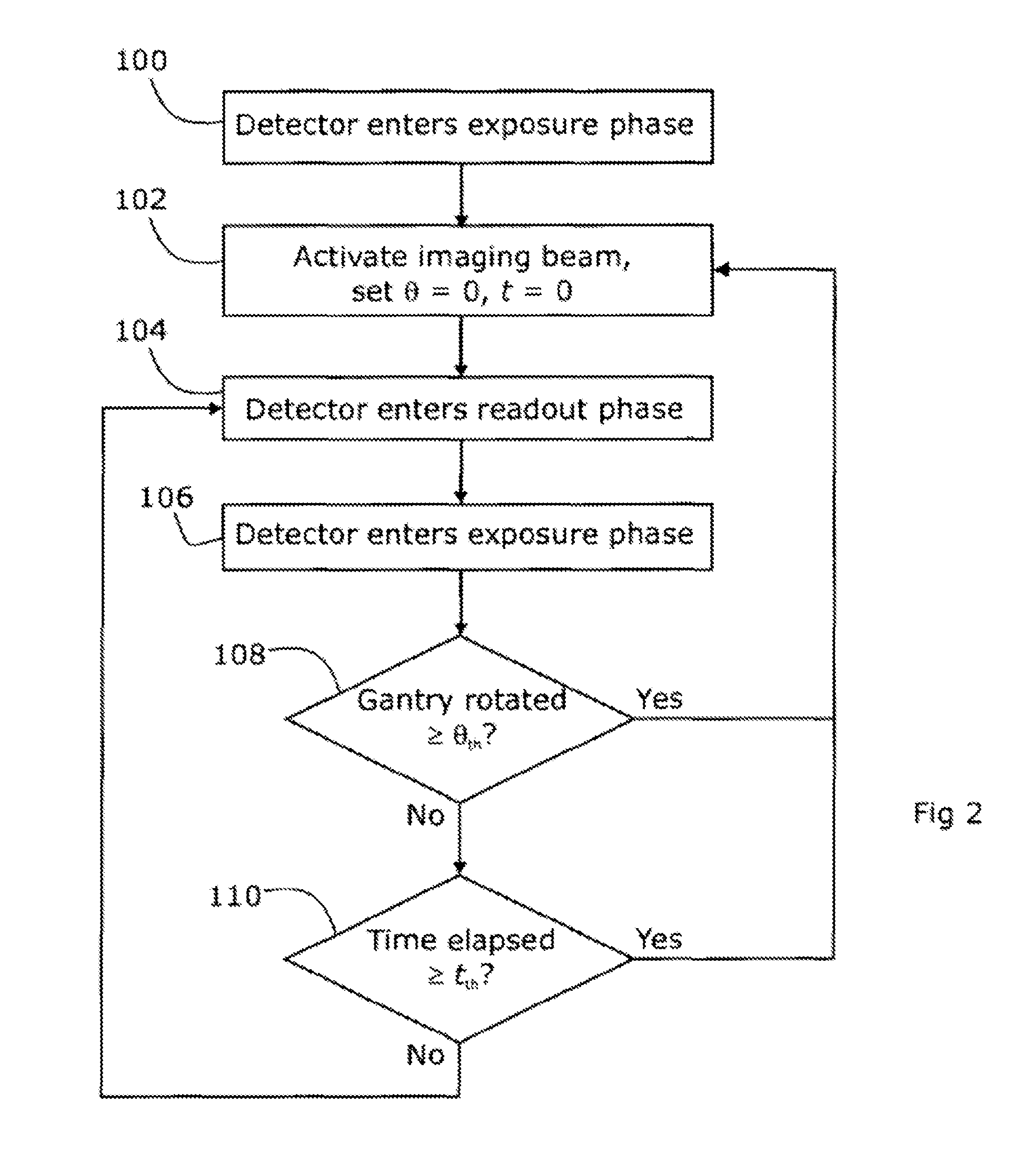
An apparatus has a patient support, a rotatable gantry supporting a source of imaging radiation, and a radiation detector that operates in a cyclical pattern of an exposure phase followed by a readout phase. For a first detector cycle in which the gantry has a first angle of rotation, the source of radiation is controlled to emit a first radiation beam pulse during the exposure phase, and respective first imaging data is read out during the readout phase. For a second, subsequent detector cycle, it is determined if the gantry has rotated through at least a threshold angular displacement relative to said first angle of rotation, and if so, the source of radiation is controlled to emit a second radiation beam pulse during the exposure phase, and respective second imaging data is read out during the readout phase.

Description

[0001]This application is a continuation of co-pending Patent Cooperation Treaty Patent Application PCT / EP2011 / 000511, filed Feb. 4, 2011 and published as WO 2012103901 A1 on Aug. 9, 2012, which is incorporated herein by reference.TECHNICAL FIELD[0002]The present invention relates to methods and apparatus for computed tomography (CT) scanning. Various embodiments are described, including methods suitable for surveillance of a patient during radiotherapy treatment.BACKGROUND ART[0003]It is known that exposure of human or animal tissue to ionizing radiation will kill the cells thus exposed. This finds application in the treatment of pathological cells, for example. In order to treat tumors deep within the body of the patient, the radiation must first penetrate the healthy tissue in order to irradiate and destroy the pathological cells. In conventional radiation therapy, large volumes of healthy tissue can thus be exposed to harmful doses of radiation, resulting in prolonged recovery p...

Claims


Application Information

Patent Timeline
Patent Type & Authority Applications(United States)
IPC IPC(8): A61B6/03
CPCA61B6/032A61B6/4233A61B6/466A61N2005/1061
Inventor KNOX, CHRISTOPHERWINFIELD, COLINBROWN, KEVIN
Owner ELEKTA AB
Learn More