Adaptive energy performance monitoring and control system

a technology of energy performance monitoring and control system, applied in the field of control system, can solve the problems of large energy consumption in the aggregate, high maintenance cost, and large and often excessive energy consumption

Active Publication Date: 2013-04-30
LED ROADWAY LIGHTING +1
View PDF109 Cites 10 Cited by
  • Summary
  • Abstract
  • Description
  • Claims
  • Application Information

AI Technical Summary

Problems solved by technology

Lighting systems cover large geographic areas and consume large amounts of energy in the aggregate.
The large geographic areas contribute to high maintenance costs since a technician often has to visit the location of each light fixture and these visits may need to be timed so the fixtures are operational (i.e., night time or off hours).
Furthermore the large geographical areas can contribute to the impracticality of metering energy usage of individual or even sets of fixtures, thus resulting typically in estimating usage.
This further contributes to large and often excessive energy consumption.

Method used


Image

  • Adaptive energy performance monitoring and control system
  • Adaptive energy performance monitoring and control system
  • Adaptive energy performance monitoring and control system

Examples


Embodiment Construction

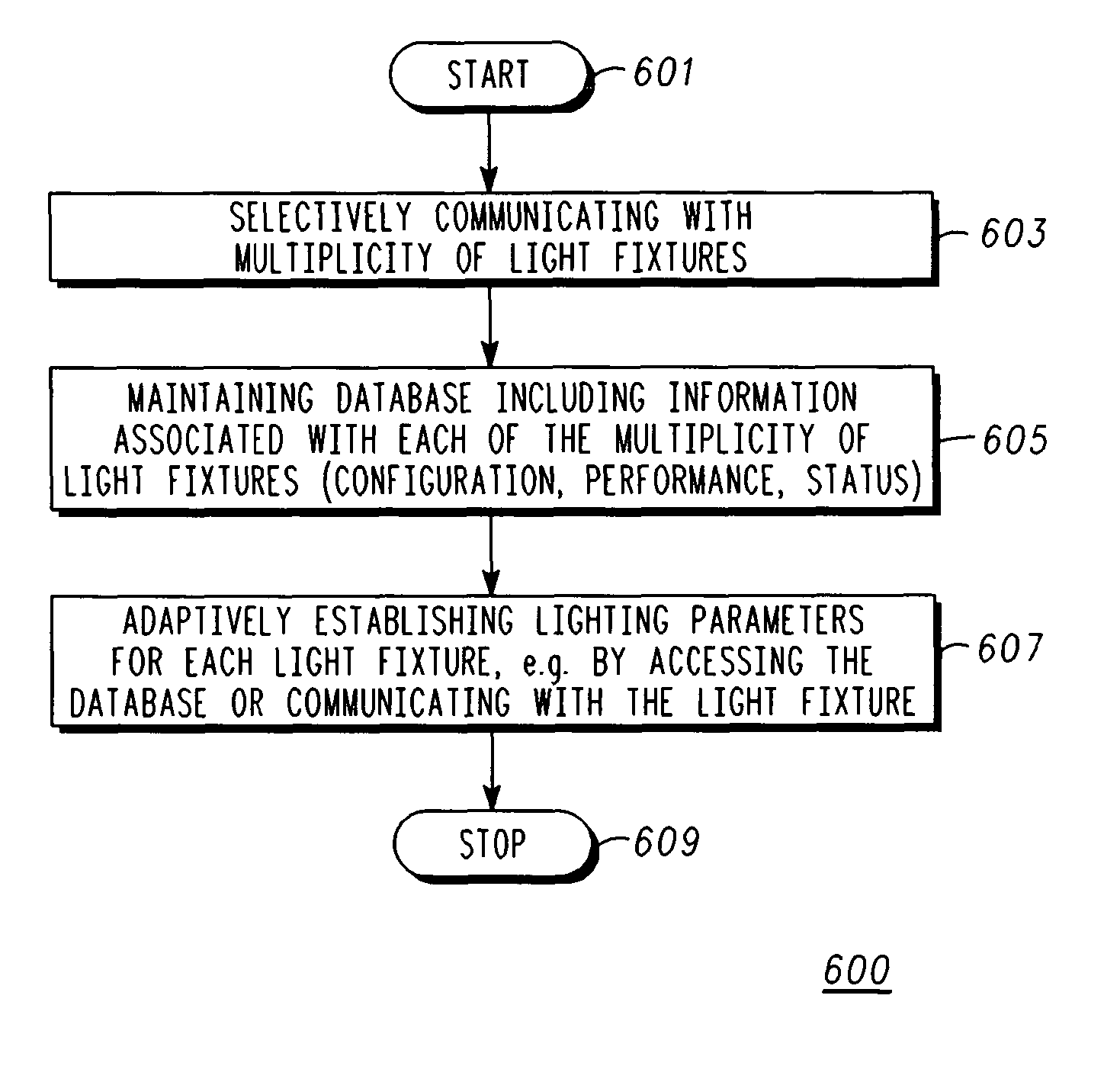
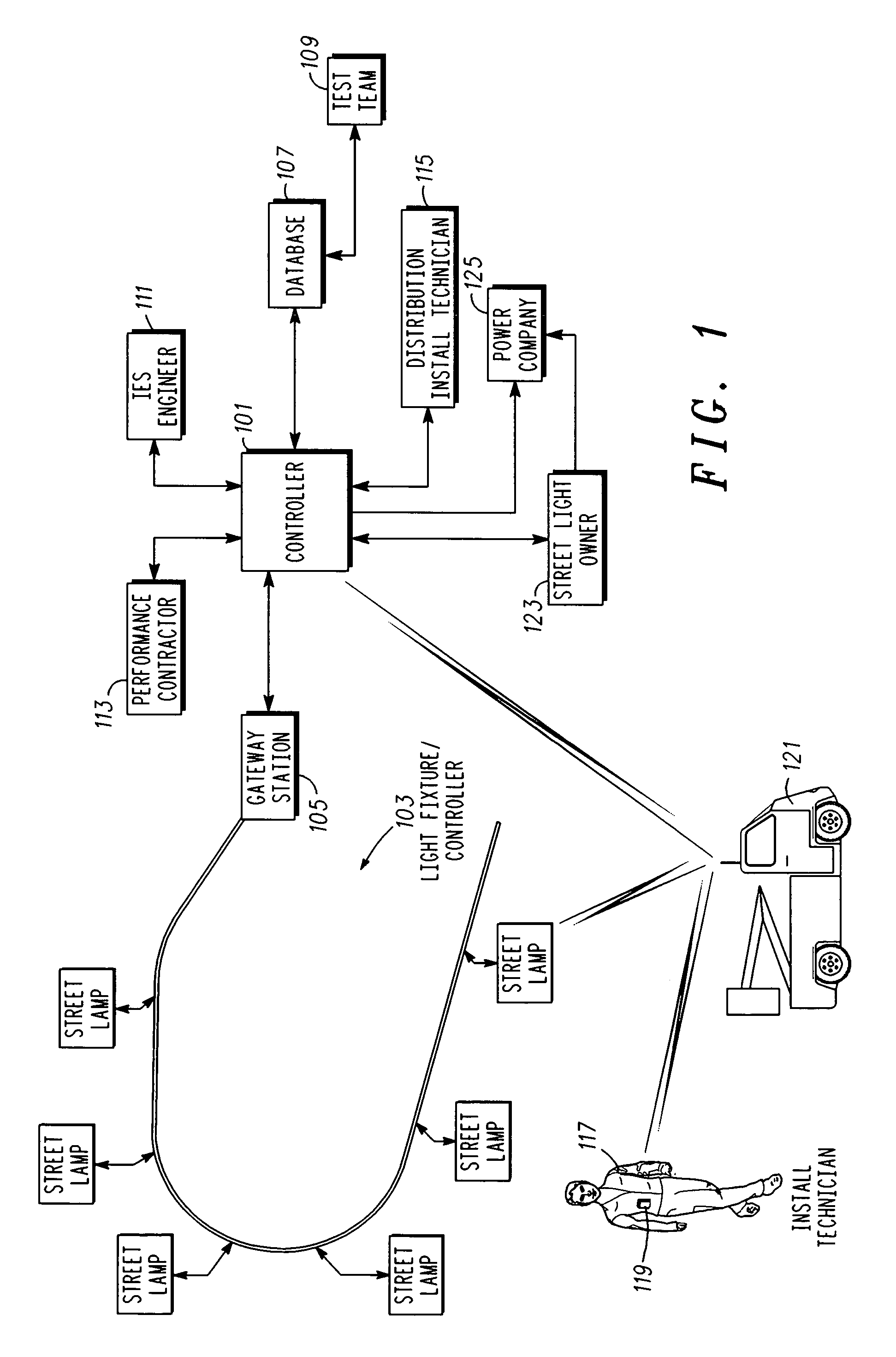
[0014]In overview, the present disclosure concerns adaptively controlling and monitoring systems, e.g., lighting systems, pursuant for example, to saving energy and maintenance costs. The systems, controllers, methods and the like discussed and described provide for entity by entity, e.g., light fixture by light fixture, control and monitoring where the control and monitoring are performed in a manner that is adaptive to the specifics of the entity, e.g. light fixture. More specifically techniques and apparatus for controlling light fixtures, such as used in street lighting or other lighting systems so that the fixtures or luminaires provide accurately controlled and specified light levels over the life expectancy of each light fixture are described and discussed.

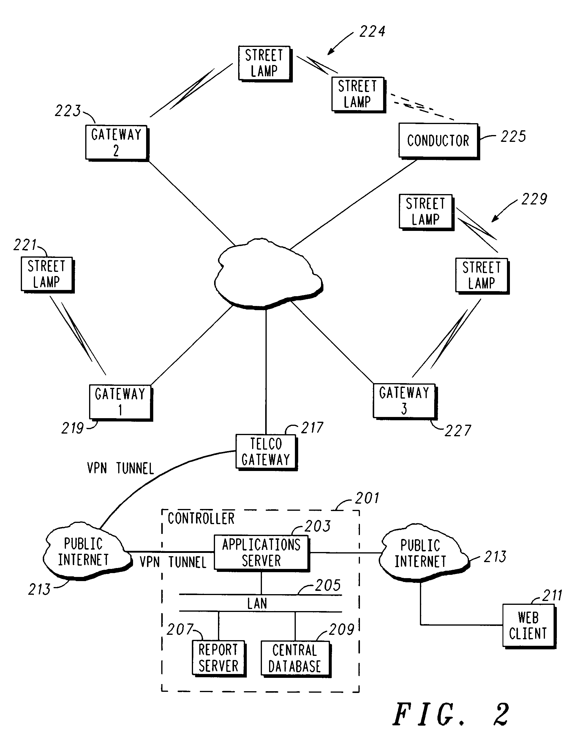
[0015]The systems of particular interest may vary widely but include outdoor and indoor lighting systems or any other system where ambient or generated light levels and accurate control and monitoring thereof on a fixture b...


PUM


Abstract

A controller is configured for and a corresponding method of adaptive monitoring and control of a lighting system are suited for adaptively establishing lighting parameters on a fixture by fixture basis. The controller includes a communication interface configured to communicate with a multiplicity of light fixtures, a memory for storing software routines and information associated with each of the light fixtures; and a processor coupled to the memory and the communication interface and configured to execute the software routines and selectively communicate with at least one of the multiplicity of light fixtures to adaptively establish lighting parameters for the at least one of the multiplicity of light fixtures. A method of facilitating the monitoring and control of the light fixture includes controlling a lamp circuit to provide one of a multiplicity of light levels; assessing performance parameters of the light fixture; and communicating with a central server.

Description

RELATED APPLICATIONS[0001]This application claims priority from Provisional Application, Ser. No, 60 / 695,252, filed on Jun. 30, 2005 and Provisional Application, Ser. No. 60 / 695,459, filed on Jun. 30, 2005, both of which are hereby incorporated herein in their entirety by reference.FIELD OF THE INVENTION[0002]This invention relates in general to control systems and more specifically adaptive monitoring and control of systems, such as lighting systems.BACKGROUND OF THE INVENTION[0003]Control and monitoring systems for systems such as lighting systems are known. Such systems can be used to turn light fixtures or luminaires on / off and monitor for basic performance, e.g., current drain, cycling conditions, number of on / off cycles and the like.[0004]Lighting systems are often designed in accordance with standards established by the Illumination Engineering Society (IES) which is an international body of lighting engineers. The standards describe appropriate lighting levels or lumen outpu...

Claims


Application Information

Patent Timeline
Patent Type & Authority Patents(United States)
IPC IPC(8): G05B11/01
CPCH05B37/0245H05B37/0254H05B37/0272H05B37/0281H05B37/034H05B37/02Y02B20/42Y02B20/72H05B47/22H05B47/18H05B47/175H05B47/16H05B47/19H05B47/10Y02B20/40
Inventor CLELAND, DONALD A.KUBEK, LAURENCE E.WONG, CAROL A.MCCARTHY, COLLEEN D.DUVAL, GORDON A.
Owner LED ROADWAY LIGHTING
Why Eureka
Try Eureka